
Low Frequency CTCSS PL Sub-Tone Audio Oscillator

The Sub-Tone Oscillator circuit utilizing the 555 timer IC operates in an astable mode, generating a continuous square wave output. The 555 timer, a highly versatile integrated circuit, is capable of producing precise timing and oscillation functions, making it suitable for applications such as tone generation in communication systems. The astable configuration consists of two resistors (R1 and R2) and a capacitor (C1), which determine the frequency of oscillation. In this design, the selected values for R1, R2, and C1 are critical in achieving the desired frequency, which falls within the CTCSS Sub-Tone Range typically used in radio communications to prevent interference from other signals.
The output from the 555 timer can be connected to the high side of the transmitter's deviation potentiometer. This connection is vital as it allows the generated sub-tone to modulate the transmitted signal effectively. The stability of the oscillator is enhanced by the comparator function of the 555 timer, which compensates for any voltage fluctuations that may occur during operation. This feature ensures that the output frequency remains consistent, providing reliable performance in communication applications.
Adjustments to the tone range can be accomplished by changing the capacitance of the timing capacitor (C1). A larger capacitor will lower the frequency, while a smaller capacitor will increase it, allowing for fine-tuning of the sub-tone to match specific requirements. Additionally, the circuit's design allows it to function as a DC Clock Pulse Generator, which can be utilized in various timing applications beyond tone generation.
Overall, this compact and efficient Sub-Tone Oscillator circuit exemplifies the utility of the 555 timer IC in generating stable frequencies for communication systems, while also being adaptable for other timing-related applications.The lf555afosc1. pdf file download is the diagram (with notations) of Sub-Tone (CTCSS or "PL") Oscillator, made with the famous 555 timer IC set up for astable-multivibrator operation. The values shown place the tone range near the center of the standard CTCSS Sub-Tone Range. You can build this circuit very small, about postage stamp size. Connecti on is made to the "high side" of your transmitters deviation pot (not at the mic input). The comparator operation of the 555 provides a measure of stability against voltage fluctuations. You can adjust the tone range with slight value changes in the. 1uf capacitor. This circuit also makes a nice DC Clock Pulse Generator by taking the output as noted. The file is in Adobe PDF format, but you can right click your mouse and save the gif file picture (shown just above) from this description page. We/I get a lot of Email from visitors who drop into these file down load description pages via a web search "engine" (like Google).
Vistors are not able to locate the file download icon for that specific description page. There is a simple way to find the file download icons on the main sonic web page. Second: Back space out the page your now looking at in your browser location line. As an example, using the description page. Remove the last portion of the web location with the keyboard back space key to read then press your Enter Key to reload the main sonic page "just in front" which would probably has the inforamation you`re looking for. This works on most of the current browsers at most web sites. 🔗 External reference
Related Circuits

This circuit is an oscillator utilizing astable mode operation, based on the 555 timer integrated circuit (IC). It functions as a free-running oscillator. The operation begins when the capacitor (C) charges towards 2/3 of the supply voltage (V+) through...
Most small internal combustion engines commonly used in model building utilize glow plugs for starting. However, glow plugs operate at a voltage of 1.5 V, while components such as fuel pumps, starter motors, and chargers typically operate at 12...
A few years ago, a decision was made to eventually replace a decades-old Nakamichi stereo system with a more mobile-friendly alternative. It became apparent that Class-D and Class-E switching amplifiers, which had been researched in the 1970s, were experiencing...
This design was developed by request of a correspondent having made a sort of LED candle and needing to switch off the LED with a puff. This simple, easy to build gadget can be useful as a prop for...
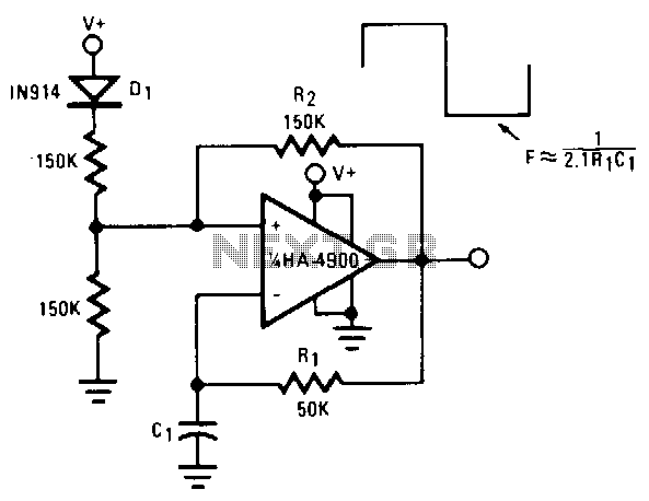
This self-starting fixed-frequency oscillator circuit provides excellent frequency stability. R1 and C1 form the frequency-determining network, while R2 delivers the regenerative feedback. Diode D1 improves stability by compensating for the difference between VaH and VsurrLY. In applications where a...
The project is a variation of the popular POV toy, commonly seen as a beginner electronics project. This year, the decision was made to create a synthesizer kit, incorporating an SPI DAC, audio amplifier, microcontroller, and buttons. Additionally, there...