
Low-volts alarm

The circuit operates by utilizing a zener diode to establish a reference voltage level. When the input voltage falls below this reference, the zener diode conducts, signaling the alarm circuit to activate. The alarm is typically implemented using a simple piezoelectric buzzer or a similar sound-emitting device.
The RC time constant, determined by the resistor and capacitor values, influences the frequency and duration of the alarm sound. In this circuit, the 39 kΩ resistor in combination with the 0.01 μF capacitor creates a time constant of approximately 0.39 milliseconds, which affects the oscillation frequency of the alarm tone produced. The resulting sound can be adjusted by changing these component values, allowing for customization based on user preference.
This voltage monitor is particularly advantageous in battery management systems where low power consumption is essential. The circuit's design ensures minimal energy draw during its idle state, making it ideal for applications where battery life is a critical factor. The simplicity of the design allows for easy integration into existing systems, providing a reliable solution for voltage monitoring in various electronic applications.This inexpensive dc supply-voltage monitor sounds a warning when the voltage falls below a preset value. It is ideal for monitoring rechargeable batteries since it draws only a few microamperes when not sounding.
The voltage at which the alarm sounds is determined by the zener diode. When the voltage falls below the zener voltage, the alarm sounds. The alarm tone is determined by the RC time constant of the 39 k resistor and 0.01 mf capacitor.
Related Circuits
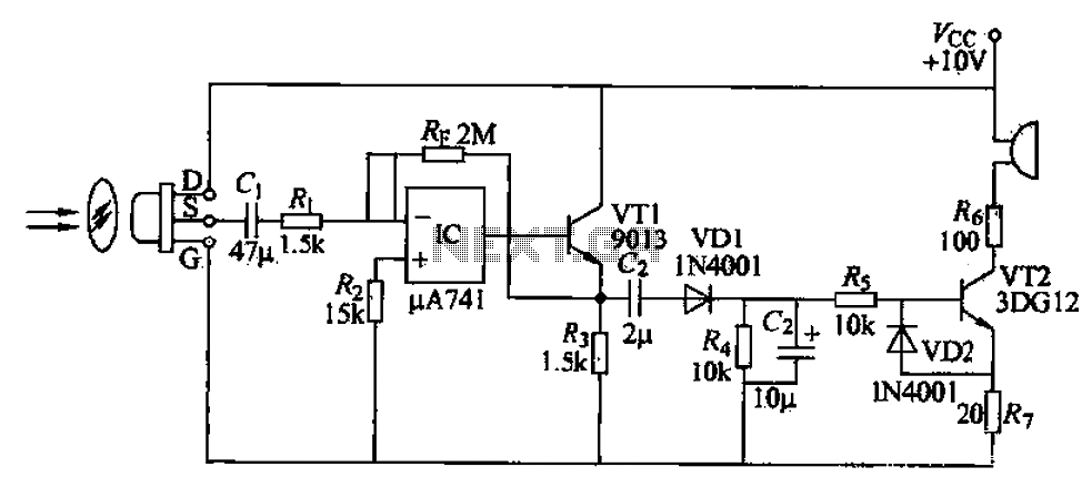
A simple burglar alarm circuit utilizes a pyroelectric sensor (IRA-E100SZI). When human movement is detected, it triggers an electric buzzer alarm. The sensor receives signals through an AC amplifier, which is then converted by a rectifier circuit into a...

A nightlight combined with a wake-up alarm has been developed. This nightlight incorporates six LEDs that activate when a photosensor detects low ambient light levels. Additionally, a buzzer plays a cheerful tune when ambient light levels increase again. The...
This simple alarm timer circuit is constructed using a 4060 integrated circuit, which features a stable oscillator with a relatively wide frequency range. The alarm timer circuit utilizes the CD4060 IC, which combines a low-frequency oscillator and a binary counter....

The following circuit illustrates a Photo Alarm Electronic Circuit. This circuit is based on the 555 Timer IC and incorporates features such as an LDR (light-dependent resistor). The Photo Alarm Electronic Circuit utilizes a 555 Timer IC configured in monostable...

In the event of a sudden power failure in an elevator, it is crucial for the duty officer in the distribution room to be alerted promptly to prevent panic among passengers trapped inside. The following describes a sound alarm...

The circuit requires two transistors to drive a relay, which acts as a switch to activate a buzzer. Any number of normally-open switches may be applied. Mercury switches should be installed to ensure they close when the steering is...