
Simple and practical circuit diagram of an elevator failure alarm

The sound alarm circuit is a critical safety feature in elevator systems, designed to provide immediate notification of power outages that could leave passengers stranded. The circuit employs a combination of timers, transistors, and relays to ensure that the alarm is activated promptly and operates effectively. The use of a 6V battery ensures that the system remains functional even during a power outage, while the charging circuit guarantees that the battery is replenished when power is restored. The integration of the NE555 timer ICs allows for precise control over the alarm duration and frequency, ensuring that the alarm is both audible and effective in alerting the duty officer. The design emphasizes reliability and safety, making it an essential component of modern elevator systems. As we all know, if the elevator power suddenly fails, the distance distribution room duty officer is not immediately found, this time, the crew was on the elevator might panic. Here are a sound alarm circuit, as shown below, as long as the elevator of a power failure, the elevator distribution room will issue a sound alarm signal. The circuit works as follows: a circuit powered by a 6V battery, AC power once the elevator failure, the circuit that is audible alarm, the alarm time can be set in advance.
Alarm to a certain time, the end of the alarm sound, the duty officer to find fault immediately. Once troubleshooting, power restoration work, reported glanced circuit is cut off, while the battery will power the AC voltage charging. On 230V AC power by the step-down transformer X1 battery charging diodes D1, D2 rectified after Manifold IC4 (LM7806) regulator, the battery via a diode D5 and RLI relay normally closed contact (N/C) for charging.
When the battery is charging, transistor T1 through the diode D4 is turned, causing the tube T2 is turned off, no current flows through the relay RL1 because without work, the result has been in a state of charge of the battery. The maximum value of the charging voltage of 6V plus D5 pressure drop. Once an AC power failure (eg open circuit), the transistor T1 off, T2 is turned on, the relay pull a job, the normally closed (N/C) contact opens make contact (N/0) is turned on, the rechargeable battery loop is cut off.
At the same time, the timer IC2 and IC3 through the relay RLI closed contact (N/0) with battery-on operation. Timer IC3 (NE555) (3) feet of the output pulse signal 1KH2 deactivated IC2 (NE555) reset terminal (4) feet, IC2 works in pulsed mode, (3) an output signal pin of IC2 via the audio amplifier IC5 amplification, push speaker sound an alarm, indicating that the AC broke down.
Related Circuits
Here, S1 and S2 are normally open, push to close, press button switches. The diodes can be red or green and are there only to indicate direction. You may need to alter the TIP31 transistors depending on the motor...
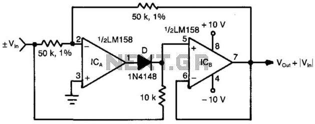
When the input voltage is positive, the output of ICA is negative, resulting in diode D not conducting; therefore, the output of ICB is positive. Conversely, when the input is negative, the output of ICA becomes positive. Diode D...
This schematic illustrates an infrared (IR) transmitter circuit utilizing an integrated circuit (IC). The circuit employs the widely recognized NE555 timer IC, which operates as an astable multivibrator to generate a signal with a frequency of 38 kHz. The...
This 1 Hz and 2 Hz generator or oscillator is constructed using a 4060 IC as the oscillator and a 14-bit counter. To achieve a 1 Hz signal from the 4060, a 1/2 4013 flip-flop is utilized. This circuit...
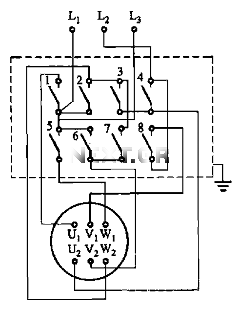
The circuit illustrated in Figure 3-36 includes the starter contact closure detailed in Table 3-1. In the figure, U1, V1, W1, and U2, V2, W2 represent the first three-phase stator windings of the motor terminals. The circuit depicted in Figure...
This simple circuit can be utilized to activate various devices, such as connecting it to microcontrollers, relays, secret alarms, or robot applications. It can also be used to turn on LED1, which remains lit as long as the metal...