
Automatic mooring light

When darkness occurs, the resistance of the LDR exceeds the value of R1, leading to an increase in voltage at pin 2 of U1 above the reference voltage of 2.5 volts. As a result, the output at pin 6 of U1 drops below 1 volt, turning on transistor Q1. The resulting base-to-emitter current flow activates transistor Q2, allowing current to flow through the lamp. This cycle repeats with the transition between day and night.
The circuit utilizes the operational amplifier U1 in a comparator configuration, where the LDR serves as a variable resistor influenced by ambient light levels. The resistors R2 and R3 are selected to create a stable reference voltage, which is essential for the proper functioning of the comparator. The output of the operational amplifier directly controls the state of the transistors Q1 and Q2, which act as switches for the lamp L1.
Transistor Q1 is configured to respond to the output voltage of U1, where a high output voltage (approximately 4.5 volts) keeps Q1 off, while a low output voltage (below 1 volt) turns Q1 on. The activation of Q1 leads to the conduction of Q2, which ultimately controls the power to the lamp. The design ensures that the lamp is turned on at night when the ambient light decreases and turned off during the day when light levels increase.
This circuit exemplifies a simple yet effective light control system, leveraging the properties of operational amplifiers and transistors to automate lighting based on environmental conditions. The use of an LDR for light detection and the operational amplifier for voltage comparison creates an efficient mechanism for controlling electrical devices based on light levels.Integrated-circuit Ul—an LF351 or 741 op amp—is used as a comparator to control the light. Resistors R2 and R3 provide a reference voltage of about 2.5 volts at pin 3 of Ul. When daylight falls on light-dependent resistor LDR1, its resistance is low: about 1000 ohms. In darkness, the LDR's resistance rises to about 1 megohm. Since Rl is 100,000 ohms, and the LDR in daylight is 1000 ohms, the voltage ratio is 100 to 1; the voltage drop across the LDR is less than the 2.5 volt reference voltage and pin 2 of Ul is held at that voltage. In that state, the output at pin 6 of Ul is positive at about 4.5 volts, a value that reverse-biases Ql to cutoff, which in turn holds Q2 in cutoff, thereby keeping lamp II off.
When darkness falls, the LDR's resistance rises above Rl's value and the voltage at pin 2 of Ul rises above the reference voltage of 2.5 volts. Ul's output terminal (pin 6) falls to less than a volt and Ql is biased on. The base-to-emitter current flow turns Q2 on, which causes current to flow through the lamp. When daylight arrives, the LDR's resistance falls sharply, which causes the lamp to be turned off, ready to repeat the next night/day cycle.
Related Circuits
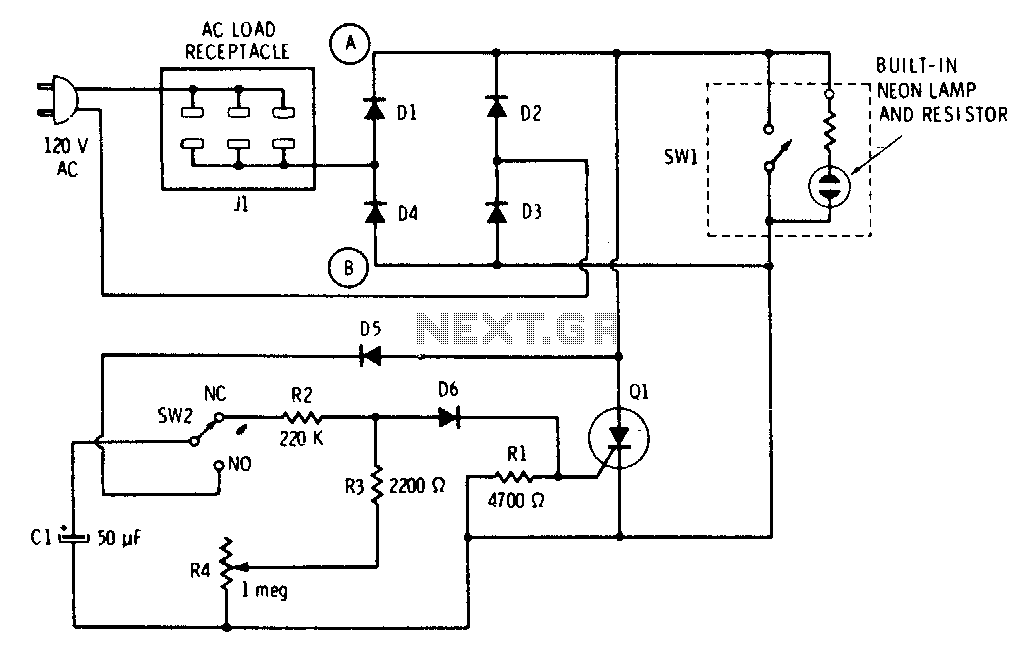
The push button and potentiometer initiate a time delay that turns a light on and then automatically turns it off again after a predetermined time. The potentiometer can be set for a delay of a few seconds to just...

The Saver V5.0 operates a simple clock emulation program that controls a night light to turn on and off at preset times, specifically from 19:00 to 22:00 daily. This design is characterized by its low cost, easy installation, lack...
This circuit is continuously connected to a mains socket and is designed to trickle charge nickel-cadmium (Ni-Cd) batteries. In the event of a power outage, the lamp automatically turns on. Alternatively, an alarm sounder can be selected instead of...
This circuit is relatively simple yet valuable, providing a high-quality interior light delay feature. This feature is commonly found in modern cars, although the automatic dimmer version is typically reserved for more expensive models. This circuit allows for the...
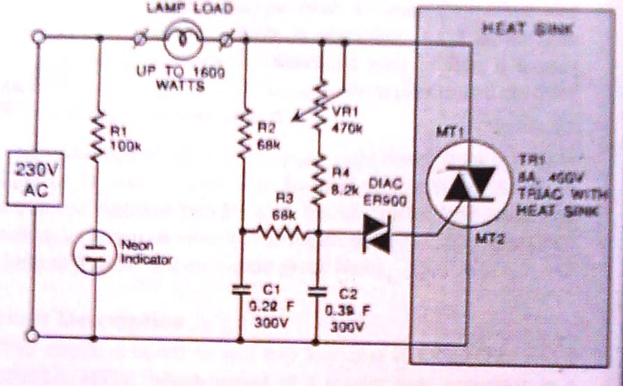
This dimmer is designed to control illumination effectively, with a power handling capacity that exceeds 1600 watts, significantly surpassing the typical 300-watt dimmers. The circuit utilizes a triac rated at 400 PIV and 8 amperes, while component VR1 allows...
The circuit of the mains current detector is shown in Figure 1. By using a few cheap diodes, a resistor, LED and LDR, a simple opto-isolated detector can be created. This entire circuit dissipates very low power, and can...