
M15m Tracking Transmitter

The M15m Tracking Transmitter circuit is designed to be compact and efficient, making it ideal for applications where space is limited, such as in model rockets or small wildlife tracking devices. The use of a 49.152 MHz crystal allows for a stable frequency output, which is crucial for reliable signal transmission. The on-off-carrier design ensures that the transmitter conserves battery life while still providing a consistent signal for tracking purposes.
To enhance performance, careful attention should be paid to the antenna design. The recommended length of 12 inches for the antenna is a compromise between size and performance, and the addition of a counterpoise can significantly improve the range. The ability to coil the antenna and counterpoise for storage adds versatility, allowing for easier integration into various payload designs.
In operational settings, the choice of receiver plays a critical role in the effectiveness of the tracking system. A receiver with CW mode capability will provide the best auditory feedback, allowing users to hear the on-off signal directly. The use of an S-meter on FM receivers can serve as an alternative method to gauge signal strength, which is particularly useful in environments with high background noise.
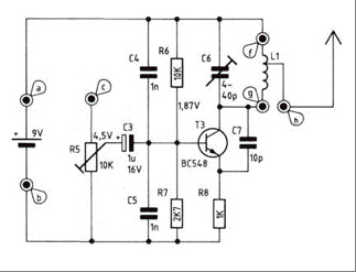
Overall, the M15m Tracking Transmitter represents a robust solution for tracking applications, combining ease of use with effective performance characteristics. Proper assembly and installation practices are essential to ensure reliable operation, and users should familiarize themselves with the nuances of radio direction finding to maximize the utility of the system.The M15m Tracking Transmitter is a modified version of the M15 Animal Tracking Transmitter. It has been designed to be used on 147. 460 MHz using an inexpensive 49. 152 computer crystal and for printed circuit board construction. The M15m transmitter is a crystal controlled on-off-carrier (OOC) transmitter designed for model rockets but suitable for wildlife, balloons and many other applications requiring a small, frequency stable transmitter. The transmitter works best with a receiver that has CW mode, however an FM receiver or scanner can be used if it has a S meter which can be observed during operation. Transmitter ground range is approximately 400 yards (5 feet above ground)*. Battery life is approximately 30 days of continuous operation. Air to ground transmission range can be substantially greater than ground-to-ground range. Also the range can be increased significantly by using a directional high gain antenna or a more sensitive receiver.
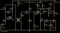
Field tests and range measurements were done with a ICOM IC-W32A transceiver with 0. 16 micro volts of receiver sensitivity through the standard 8 inch antenna. 30 days (#394, 1. 5 volt silver oxide watch battery) Recommended Receiver requirements: 144. 455 - 147. 460 MHz. , 0. 16microvolts sensitivity or better CW mode preferred for audio or can use S-meter on FM radio, 2-meter amateur radio, and some scanners. Receiver Antenna: directional antenna recommended but not required. Other: Knowledge of radio direction finding The transmitter is a crystal controlled 147. 460 MHz transmitter. The transmitter turns on and off at a ½ to 1 second interval. The circuit is designed to use a low cost computer crystal 49. 39 Mhz (3rd over tone), However, custom crystals can be used if other frequencies are desired. If other frequencies are desired a 3rd overtone series crystal can be ordered from a crystal manufacture.
To achieve adequate performance you will need a receiver with at least 0. 16 micro volts of sensitivity. Most 2-meter Amateur (ham) radios are at least this sensitivity. Scanners may or may not be sensitivity enough. Since this transmitter is not modulated you will need a receiver with CW mode if you want to hear the signal. If you receive the signal on a FM receiver (like the ICOM IC-W32A transceiver the author used to test the transmitter) you will be able to observe the presence of the signal by watching the S-meter.
The sound you will hear on a FM receiver will be a decrease in the background noise when the transmitter turns on. The transmitter antenna is 12 inches of 20 to 24 gauge common "hook-up" wire. The range of the transmitter can be doubled by attaching a wire (counterpoise) of the same length as the antenna from the positive supply extending in the opposite direction of the antenna.
Both the counterpoise and the transmitter antenna can be coiled on a ½ to inch diameter to shorten the length of the antenna and to allow storage inside a payload compartment. Coiling the antenna does shorten the range of the transmission. A method that works well in most cases for model rocket use is to suspend the module from the nose cone by the coiled counterpoise, and extend the transmitter antenna into the payload compartment or out the bottom of the payload compartment and along side the fuselage.
The coiled counter poise provides a shock absorbing function during lift-off. NOTE: Be aware that the small size of the circuit requires that GREAT CARE be taken to prevent solder bridges when soldering. Use a 20 to 40 watt soldering iron with a pencil sharp point; trim all leads after soldering and check each solder joint with a magnifying glass for bridges and solid connection.
Please refer to the "Component Side View" illustration when installing parts. All components are installed on the blank side of the board (not the foil side). When installing components bend the leads to match the hole spacing. Push the leads throu 🔗 External reference
Related Circuits
Building an FM radio transmitter for an iPod is straightforward. It features a power switch located at the bottom, allowing the user to turn it on and adjust their radio and transmitter to the desired frequency. A copper wire...
These do-it-yourself FM transmitters are relatively simple to construct and provide a satisfying experience when music is played through the radio receiver. Comments and links to additional designs that are not included in the best list are welcome. FM transmitters...
The RF oscillator employs inverter N2 and a 10.7 MHz ceramic filter to drive the parallel configuration of inverters N4 to N6 via N3. Due to the parallel arrangement of these inverters, the output impedance is low, allowing for...
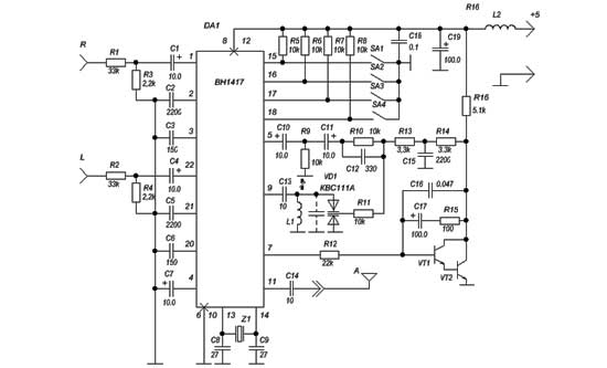
This is the BH1417 USB FM Transmitter featuring a built-in PLL circuit. It converts low-frequency signals into high-frequency signals, allowing any audio device with FM radio capabilities (such as stereo systems, car CD players, MP3 players, and DVD players)...
A simple FM transmitter links your home-entertainment system to a portable radio that can be carried around the house and into the back yard. For example, you can play music on the CD changer in your living room, and...
The TV transmitter described utilizes UK standard 1 FM modulation for sound and PAL modulation for video. The audio signal to be modulated is first amplified using transistor Q1 and its associated components. Transistor Q2 serves dual functions: generating...