
Single Chip FM Transmitter

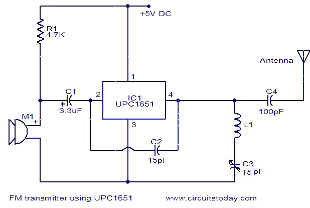
The described FM transmitter circuit functions as a bridge between a home entertainment system and a portable radio, allowing for seamless audio transmission throughout various spaces. The core component of this transmitter is IC1, a voltage-controlled oscillator (VCO) that utilizes an integrated varactor diode to modulate its frequency. This design enables the circuit to operate within the FM band, making it suitable for broadcasting audio signals.
The frequency of oscillation is primarily determined by inductor L1, which is specified at a value of 390nH. This inductance value is critical as it establishes a nominal frequency of approximately 100 MHz, which falls within the typical FM broadcasting range. The choice of this frequency is important to ensure compatibility with standard FM receivers, allowing for effective transmission and reception of audio signals.
Potentiometer R1 plays a pivotal role in tuning the transmitter to different channels across the FM band. By adjusting this potentiometer, the user can vary the voltage applied to the varactor, which in turn alters the capacitance and modifies the oscillation frequency of the VCO. This feature enables the user to select an appropriate channel that minimizes interference from other radio stations, thereby enhancing audio clarity and quality.
Additional components that may be present in the circuit include bypass capacitors to stabilize the power supply to the VCO, as well as coupling capacitors that ensure proper signal transmission while blocking DC components. An antenna, typically a simple wire or a whip antenna, is also essential for radiating the modulated signal into the surrounding environment, allowing the portable radio to receive the transmitted audio.
Overall, this simple FM transmitter circuit exemplifies an effective solution for wireless audio distribution, leveraging basic electronic components to achieve functionality that enhances the enjoyment of audio content throughout a home or outdoor setting.A simple FM transmitter links your home-entertainment system to a portable radio that can be carried around the house and into the back yard. For example, you can play music on the CD changer in your living room, and listen to it on a portable radio by the back-yard barbeque.
IC1 is a voltage-controlled oscillator with integrated varactor. Its nominal frequency of oscillation is set by inductor L1, and a 390nH value places that frequency at 100MHz. Potentiometer R1 then lets you select a channel by tuning over the FM band of 8 🔗 External reference
Related Circuits
This is a highly stable, harmonic-free, long-range FM transmitter circuit designed for FM frequencies between 88 and 108 MHz. It is capable of covering a range of up to 5 km. The FM transmitter circuit operates within the designated frequency...
The simplicity of this transmitter, combined with its high performance, makes it particularly interesting. It has an output power of approximately 30 W, and under normal conditions, with the appropriate antenna and handling, it can achieve a range of...
The circuit diagram of an FM transmitter utilizes the IC UPC1651, which is a wideband UHF Silicon MMIC amplifier. This integrated circuit features a broad frequency response of up to 1200 MHz and a power gain of up to...
The audio circuit described is a microphone utilizing two 2N3904 transistors as the audio preamplifier. The audio/microphone gain is adjustable via a 5k preset potentiometer. The circuit employs a Colpitts oscillator for frequency generation, which is free-running and operates...
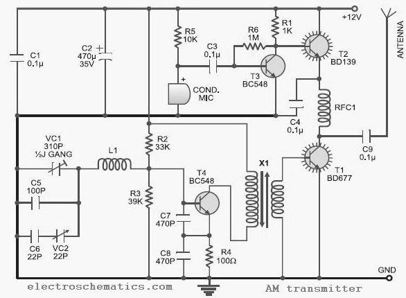
This low-cost AM transmitter is tunable from 10 to 15 MHz with the assistance of a ½J gang condenser VC1, which sets the carrier frequency of the amplitude modulation transmitter in conjunction with inductor L1. Frequency trimming can be...
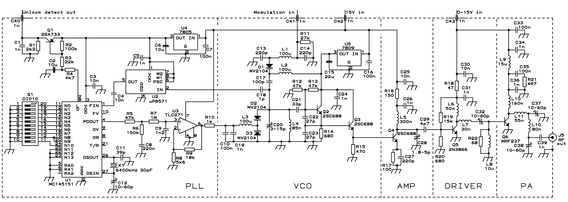
The PLL transmitter exciter is designed to provide a stable, low noise, frequency-selectable RF signal, which is amplified to a controllable output power sufficient to drive a power amplifier. It utilizes a PLL frequency synthesizer based on the MC145151,...