
Magic Sinewave Analysis using SPICE and a Simple Inverter Circuit

This document discusses the analysis of a sinewave signal generated by a simple inverter circuit using SPICE simulation software. The inverter circuit is designed to convert a DC input voltage into an AC output voltage, producing a sinewave signal that can be utilized in various applications.
The circuit typically includes essential components such as a DC power supply, an inverter (which may consist of transistors or operational amplifiers), and passive components like resistors and capacitors. The inverter's operation is based on switching principles, where the DC input is periodically inverted to create an alternating current (AC) output.
In the SPICE simulation, the circuit is modeled to observe the output waveform characteristics, including amplitude, frequency, and distortion. The simulation allows for the adjustment of component values to optimize performance and analyze the effects of different configurations on the sinewave output. By examining the results, engineers can gain insights into the circuit's behavior and make informed decisions regarding design improvements.
The analysis may also include frequency response testing, where the inverter's output is evaluated across various frequencies to determine its efficiency and stability. Additionally, the simulation can highlight potential issues such as clipping or phase distortion that may arise during operation.
Overall, this analysis serves as a valuable tool for understanding the behavior of inverter circuits and the generation of sinewave signals, facilitating advancements in electronic design and applications.Magic Sinewave Analysis using SPICE and a Simple Inverter Circuit. 🔗 External reference
Related Circuits
The circuit has been designed for telephone apparatus to indicate an incoming call as it rings using an LED for visual indication. BC550, an NPN general-purpose transistor, is utilized in the design. The circuit operates by detecting the ringing voltage...
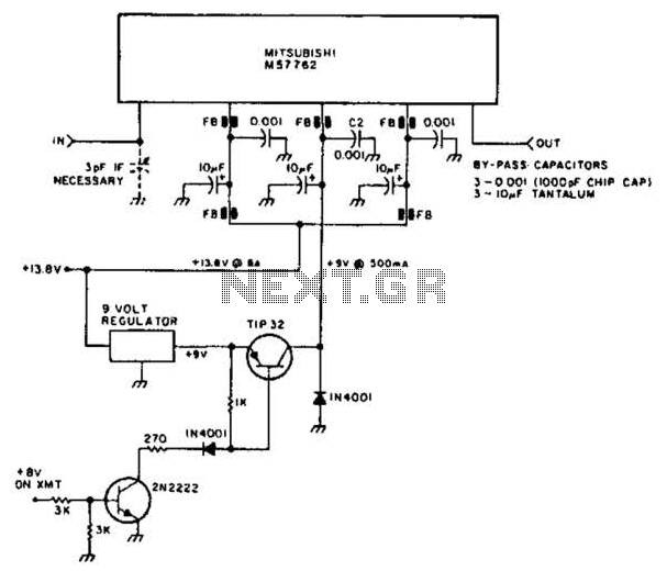
Using a Mitsubishi M57762 amplifier module, this amplifier delivers 20 W output at 1296 MHz. A single 12 V nominal power supply can be used. The Mitsubishi M57762 is a high-performance RF amplifier designed for applications requiring significant power output...
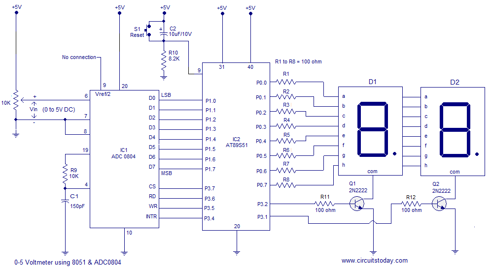
A simple 0-5 digital voltmeter utilizing the 8051 (AT89S51 microcontroller) is presented, accompanied by a circuit diagram and assembly language (ASM) code. This digital voltmeter is designed for straightforward voltage measurement. The circuit employs an AT89S51 microcontroller, which serves as...
This circuit detects the dial tone from a telephone line and decodes the keypad pressed on the remote telephone. The dial tone heard when picking up the phone is known as Dual Tone Multi-Frequency (DTMF). The term is derived...
Fans can be controlled remotely with a switch that allows for speed adjustments, and this remote control can also be integrated with other household switches. Its primary feature is the use of a sub-transmission ultrasonic transmitter, which operates without...
Motor Bike Headlight Controller Circuit. This circuit automatically turns a motorcycle's headlight on and off, independently of both the light and ignition switches, provided the battery is fully charged. The first stage... The motorcycle headlight controller circuit is designed to...