
magnet charger

The circuit design for rejuvenating the magnets in Bulle clocks presents a complex yet efficient method for restoring magnetic functionality. The use of a TRIAC allows for high current switching, which is essential given the significant demands of charging the magnet. The ballast resistor plays a crucial role in protecting the circuit from excessive current draw during initial activation, ensuring that the components do not exceed their rated specifications.
The bridge rectifier is a vital component in this setup, as it converts the AC voltage from the transformer into a stable DC voltage, which is necessary for charging the capacitors effectively. The substantial capacitance of the two 100,000uF capacitors provides a large reservoir of energy, allowing for a rapid discharge into the coil when needed. The design of the busbars ensures minimal resistance and heat generation during operation, which is critical for maintaining performance and safety.
The SCRs are strategically chosen to handle the peak currents generated during the discharge process. Their arrangement allows for a significant current to flow through the coil, revitalizing the magnet effectively. The inclusion of resistors not only balances the load across the SCRs but also acts as a safeguard against potential overcurrent situations, enhancing the reliability of the circuit.
Overall, this circuit exemplifies the integration of various electronic components to achieve a specific goal: the rejuvenation of magnets in vintage timepieces. It highlights the importance of careful design considerations in high-current applications, ensuring both functionality and safety in the process.It is fairly safe to say that most Bulle clocks will need their magnet rejuvenated before they will run properly from the normal single 1. 5V cell. The first "real" magnet material was cobalt-chrome steel, in 1921 [ 1 ]. Prior to that, carbon steel was hardened by heating and quenching, and was the basis of most magnets used.
Modern magnetic material commenced in around 1932 with the invention of Al-Ni-Fe (aluminium, nickel, iron) which later became Alnico (aluminium, nickel, cobalt). Alnico was considered a quantum leap above earlier materials. It wasn`t until some time later that today`s really powerful magnetic materials became generally available.
So-called rare-earth magnets were not produced commercially until the 1960s, with Samarium-Cobalt being the first offering. The most powerful magnets currently available are neodymium (neodymium-iron-boron, NdFeB) - these were invented in 1983, but were not readily available until some time later - well after Bulle clocks ceased production.
[ 2 ] The way any magnet is `charged` is to subject it to an intense magnetic field - the more powerful the field, the better. It is not uncommon to simply wind a coil around the magnet and briefly connect it to a car battery, but this method is fraught with danger.
Should the `contact` end of the wire become welded to the battery terminal, the coil and its supply wires will probably melt. The molten metal droplets can cause much damage to feet, arms, hands and the car`s paintwork, and the arc has a very high ultraviolet content and can damage your eyes.
As a result (and also because I had almost everything I needed in my junkbox), I decided to put a charger together. Bear in mind that this will be an extremely expensive project if you have to purchase everything new.
Even if you can get the bits from eBay, it will still be expensive. The circuit diagram is shown above. A TRIAC is used to switch the AC, because the peak charging current is far too high for any small push-button switch. The ballast resistor reduces the current to a manageable level, but it`s still around 15A when the "Charge" button is first pressed.
The only things limiting the current are the transformer`s winding resistance, and the ballast resistor. The TRIAC I used is now obsolete, but is rated for 400V and 25A continuous current. Peak current is 250A, and the transformer can`t supply anywhere near that. Any TRIAC with similar ratings will be fine. A normal (cheap) 25A bridge rectifier converts the AC into DC, and this is stored in the two 100, 000uF (100mF) capacitors.
These are very substantial devices indeed, with heavy duty screw terminals. The two are joined using two aluminium busbars, 3mm thick and about 20mm wide. Four 11A (125A peak) SCRs are used to dump the full charge in the capacitors into the coil that is wrapped around the magnet to be revitalised. The four 0. 5 Ohm resistors serve two purposes. Firstly, they force the SCRs to conduct more or less equally, since the internal resistance of an SCR is extremely low - well below 0.
5 Ohm. Secondly, the resistors limit the peak current. With the values shown, the theoretical peak current through each SCR is 150A (75V and 0. 5 Ohm), but it is actually somewhat less. A measurement taken on the unit shows the peak current through each SCR and resistor to be around 120A - the total peak current is 4 times this, or 480A. The total curr 🔗 External reference
Related Circuits

This circuit generates an intense magnetic pulse by discharging a charged capacitor through a loop-shaped inductor, resulting in the creation of a strong magnetic field. However, the circuit tends to damage a 555 timer chip positioned slightly above the...
The gelled lead-acid battery charger circuit diagram enables rapid charging of gelled lead-acid batteries and automatically shuts off upon reaching full charge. Initially, the charging current is maintained at 2 A; however, as the battery voltage increases, the current...
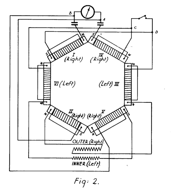
A potential source of quiet and limitless energy for submarine propulsion is described. This hexagonal configuration of coils and magnets, along with two "rotating" sub-circuits, operates without an external power source. Despite this, it seemingly generates or transduces power...
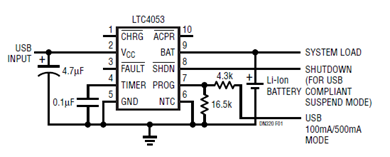
The schematic presented illustrates a minimal component solution for a USB battery charger utilizing the LTC4053 integrated circuit (IC) to create a fully compliant USB charger. This IC functions as a standalone linear charger designed for lithium-ion (Li-ion) batteries,...
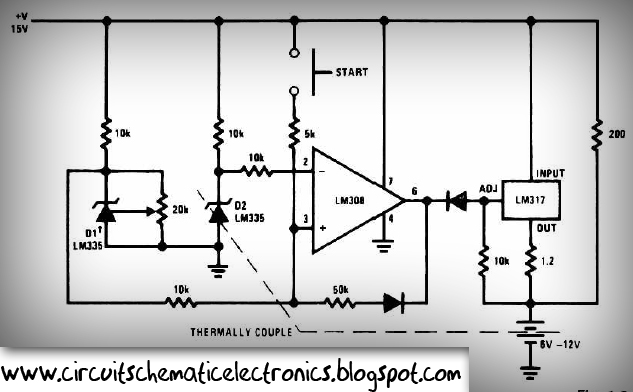
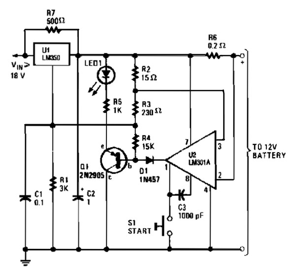
This circuit is designed for rapid battery charging. It is recommended for those who require a faster charger. The charger operates at a low temperature of 5 degrees Celsius. The input voltage is 15 volts DC, while the output...
Solar battery charger schematic and description. This solar battery charger circuit is capable of charging a 12V lead-acid battery or sealed lead-acid (SLA) battery. The solar battery charger circuit is designed to convert solar energy into electrical energy for charging...