
sound sensor schematics

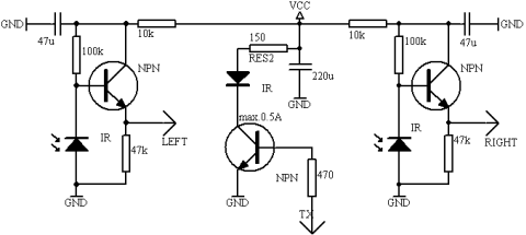
The sound sensor schematic operates by detecting sound levels in the environment and activating a relay based on the intensity of the sound. The core component, an integrated circuit, serves as the sound detection unit. It converts acoustic signals into electrical signals, which are then processed to determine if the sound exceeds a predefined threshold.
The two transistors in the circuit function as amplifiers and switches. When the input from the IC indicates that the sound level is sufficient, the first transistor is triggered. This, in turn, activates the second transistor, which controls the relay. The relay can be used to switch on or off various devices, such as alarms or lights, depending on the application.
The inclusion of a variable resistor (VR) in the design allows for fine-tuning of the sensitivity of the sound detection. By adjusting the VR, the threshold for sound detection can be modified, enabling the user to set the circuit to respond to softer or louder sounds as needed.
This schematic is advantageous for various applications, including security systems, sound-activated lighting, and other automation tasks. Its simplicity and effectiveness make it accessible for individuals with basic electronic skills, promoting ease of construction and implementation.Here is simple sound sensor schematic, it`s use only one IC and and two transistor to drive the relay. this schematics can change the sensitivity using VR resistor also. I think this schematics is very usefull and can build anyone. 🔗 External reference
Related Circuits
This circuit functions to monitor the duration of occupancy in a toilet, activating an alert if the time spent exceeds a predefined limit. The components involved include a resistor, integrated circuit (IC), capacitor, and transistor. The occupancy monitoring circuit is...
The schematic diagram described here is a TMP01 Celsius Scale Temperature Sensor circuit. This circuit is used to convert the VPTAT output voltage. The TMP01 is a temperature sensor integrated circuit designed to provide an accurate temperature measurement in Celsius....
This circuit operates using ultrasonic sound, which is sound at frequencies above 20 kHz, making it inaudible to humans. The circuit generates ultrasonic sound frequencies between 40 kHz and 50 kHz. Similar to other remote control systems, this circuit...
This chapter contains circuit diagrams for several power supplies designed for pulsed solid-state lasers. These include units suitable for driving the widely used Hughes ruby and YAG rangefinder laser assemblies, one utilizing the flash from a disposable pocket camera,...
This simple circuit, as shown in the schematic diagram, activates a switch using sound. It can be utilized for various applications, such as automatic sound-controlled disco lights or a car's LED light show. The transistor Q1 amplifies the audio...
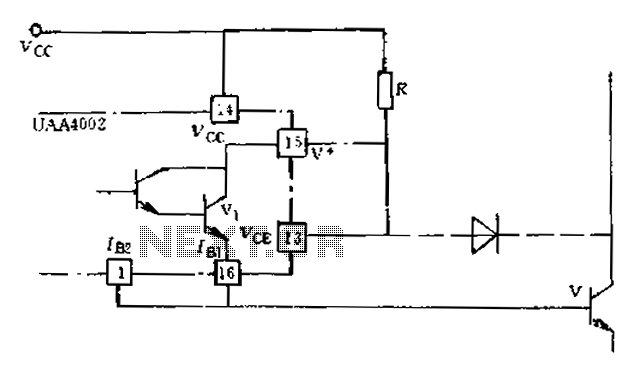
Anti-saturation devices have been removed from the UAA4002 routine applications. The base current of the switching transistor, which is driven by another transistor, is automatically adjusted. This adjustment allows the power transistors to operate in critical saturation. However, when...