
Magnetic Reed Switch Alarm

The circuit design consists of various components that work together to detect unauthorized access and trigger an alarm. At its core, the system typically utilizes a motion sensor or a magnetic switch. For home installations, a magnetic reed switch can be placed on the door or window frame, with a corresponding magnet on the door or window itself. When the door or window is opened, the magnet moves away from the switch, causing a change in the circuit state, which activates the alarm.
For portable applications, such as in handbags, a compact motion sensor can be integrated into the bag's lining. This sensor detects movement or tampering, triggering the alarm when it senses an unauthorized attempt to access the bag. The alarm signal can be generated using a piezo buzzer or a small speaker, producing a loud sound to deter potential thieves.
Power for the circuit can be supplied by batteries for portability, or it can be hardwired for home installations. A power management module may be included to optimize battery life and ensure reliable operation. Additionally, a simple control interface, such as a toggle switch or a remote control, allows the user to easily activate or deactivate the alarm system.
In summary, the described alarm circuit is a versatile security solution that can be adapted for various applications, providing effective monitoring and protection for both homes and personal belongings.This circuit is made to be an alarm, both for home and handbags. If it is installed for home it will placed on door or windows, and if it is installed for bags. 🔗 External reference
Related Circuits

A preamplifier for magnetic pickups of record players is presented. The uA 741 is utilized as an AC-coupled non-inverting amplifier operating on a single supply. The amplifier gain is determined by the feedback components, where C2 manages the low-frequency...
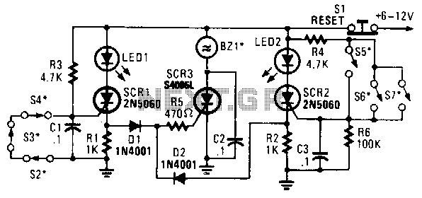
In this circuit, a low-powered silicon-controlled rectifier (SCR) is utilized to trigger a higher-powered SCR. When a switch is opened (S2, S3, S4) or closed (S5, S6, S7), either SCR1 or SCR2 is activated. This action subsequently triggers SCR3...

This Arduino-based project involves constructing a lamp with various light displays, including a color sequencer, dimming light, color chaser, and firelight, all controlled by a touch bar on the circuit board. The design adopts a minimalist approach, incorporating only...
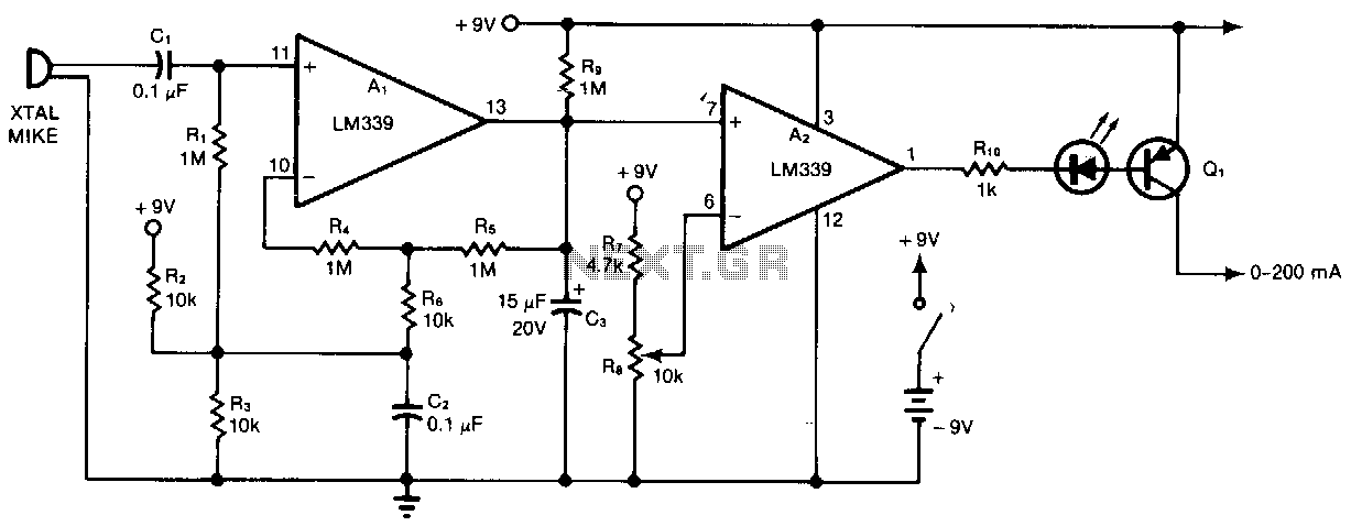
Al and A2 are two sections of a quad comparator. The first section, Al, functions as an amplifier and detector. Resistors R5 and R6 set the gain at 100; the output of Al is an open collector to negative-peak-rectify...

This is a simple electronic circuit for a clap switch project. It is suitable for beginner electronics learners who enjoy experimenting with new projects. The circuit can turn on or off a 220V electronic device, such as a fan...
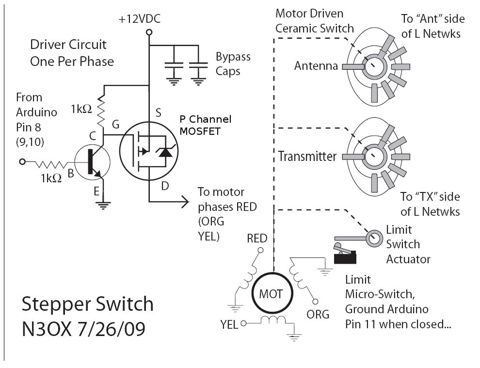
Information is needed regarding a circuit to manage the Remote Coax Ameritron RCS-10, as no diagram can be found on Google. The Ameritron RCS-10 is a remote coax switch designed for amateur radio applications, allowing users to control multiple antennas...