
Magnetic pickup pre-amplifier circuit

The described preamplifier circuit is essential for enhancing the signal from magnetic pickups found in record players, which typically produce low-level outputs. The uA 741 operational amplifier is a widely used component due to its versatility and performance in audio applications. As an AC-coupled amplifier, it allows for the amplification of AC signals while blocking any DC offset that may interfere with the audio signal.
The selection of feedback components is crucial for tailoring the frequency response of the amplifier. Capacitor C2 plays a significant role in defining the low-frequency cutoff point, ensuring that unwanted low-frequency noise is attenuated, which is particularly important for preserving audio fidelity. Capacitor C4, on the other hand, acts to limit high-frequency gain, preventing distortion that could arise from excessive amplification of high-frequency signals, which are often present in the output of magnetic pickups.
The voltage divider formed by resistors R3, R4, and R5 is designed to set the bias point of the non-inverting input. By establishing a bias voltage of approximately half the supply voltage, the circuit ensures that the output signal can swing equally above and below this midpoint, maximizing the dynamic range of the amplifier output.
To further enhance the performance of the preamplifier, R5 and C3 work together to create a low-pass filter that mitigates power supply noise and hum. This is particularly beneficial in environments where multiple circuits may be powered from the same supply, as it helps to isolate the preamplifier from potential interference caused by other components.
Overall, the circuit design effectively addresses the challenges associated with amplifying low-level audio signals from magnetic pickups while ensuring high fidelity and minimal noise interference. This makes it an integral component in high-quality audio playback systems.A preamplifier for magnetic pickups of record players is shown here. The uA 741 is used as an AC coupled non-inverting amplifier operating on a single supply. The amplifier gain is decided by the feedback components in which C2 controls the low frequency roll-off characteristics while C4 reduces the gain at high frequency end to compensate for the p ickup characteristics. R3, R4 and R5 form a voltage divider to give a bias of about half the supply voltage to the non-inverting of uA741. The output at pin6 therefore stands at half the supply voltage. R5 and C3 form a supply line filter to reduce the hum level ans also to eliminate growling in case the preamplifier circuit is operated on a common supply with other circuits.
🔗 External reference
Related Circuits
This is a single-channel (on/off) universal switch that can be used with any infrared remote control operating within wavelengths of 850-950 nm. The single-channel universal switch functions as a simple on/off control mechanism, allowing users to operate electronic devices remotely...
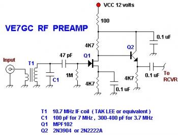
This is a simple VE7GC Popcorn RF preamplifier designed by Dick Pattinson. The circuit features a single tuned circuit at the input stage, allowing direct connection to a mixer or product detector in a straightforward receiver project. Adjustable RF...
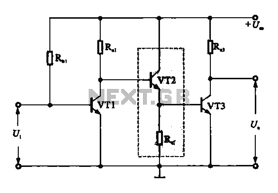
A DC-coupled multi-stage amplifier circuit consists of multiple stages of amplification using a DC-coupled configuration. Each stage utilizes NPN-type transistors, which are designed to maintain appropriate operating points at the base of each stage. As the signal progresses through...

Magnetic stimulation is a non-invasive method used to stimulate the brain and peripheral nervous system through induced currents. When targeting the brain, it is commonly referred to as Transcranial Magnetic Stimulation (TMS). The fundamental principle involves a time-varying pulse...
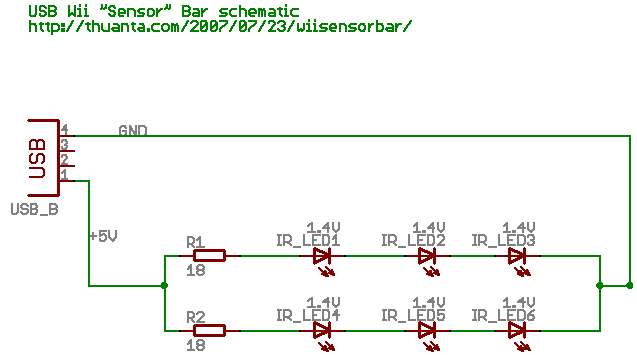
The following circuit illustrates the Wii "Sensor" Bar Project Circuit Diagram. Features include a series of infrared LEDs positioned at both ends of the bar, which emit infrared light. The Wii Sensor Bar is a crucial component for the Wii...
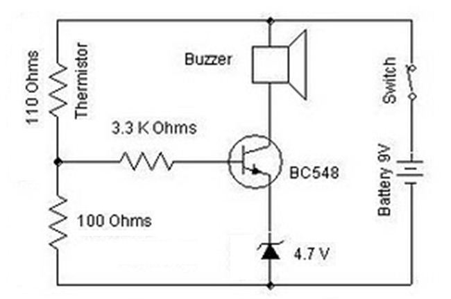
A heat sensor circuit can be utilized to control any device using a heat sensor. In this circuit, a thermistor and a resistor are connected in series, forming a potential divider circuit. The thermistor is of the Negative Temperature...