Mains-operated Capacitive Sensor

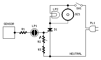
This very simple circuit acts as a high sensitivity capacitive sensor. Lamps and/or Buzzers are operated at half the mains supply voltage when a part of the human body comes in contact with the sensor or approaches it at a close distance. The circuit can be used as an alternative to the Door Alarm or Capacitive Sensor circuits, already available on this website.
The described circuit functions as a capacitive touch sensor that responds to the proximity of a human body, effectively detecting changes in capacitance when a conductive object, such as a human hand, approaches or touches the sensor. The circuit typically operates at half the mains supply voltage, allowing it to control low-power devices like lamps and buzzers safely.
The core component of the circuit is a capacitive sensing element, which can be made from a conductive plate or a PCB trace. This element is connected to a signal processing unit, often utilizing an operational amplifier or a microcontroller to interpret the changes in capacitance. When a person approaches the sensor, the capacitance increases, triggering the output of the circuit.
To ensure reliable operation, the circuit may include a resistor-capacitor (RC) network that helps filter out noise and stabilize the sensing signal. The output stage can be designed using a relay or a transistor to switch the connected load, such as a lamp or a buzzer, on or off based on the detected proximity.
In practical applications, this circuit can serve as an alternative to traditional door alarms or other capacitive sensor systems. It is particularly useful in environments where touchless operation is preferred, enhancing user convenience and safety. Proper calibration and placement of the sensor are crucial to optimize its sensitivity and ensure effective operation in various settings.This very simple circuit acts as a high sensitivity capacitive sensor. Lamps and/or Buzzers are operated at half the mains supply voltage when a part of the human body comes in contact with the sensor or approaches it at a close distance. The circuit can be used as an alternative to the Door Alarm or Capacitive Sensor circuits, already available on this website.
🔗 External reference


