
2002 blazer: 02 sensor circuit malfunction solenoid it warms

The described issues with the 2002 Blazer involve two primary components: the Heated Oxygen Sensor (HO2S) and the transmission shift solenoid. The P0155 code indicates a fault in the heating circuit of the HO2S located in Bank 2, Sensor 1. This sensor plays a crucial role in monitoring the oxygen levels in the exhaust, thereby aiding in the engine's air-fuel mixture regulation. A malfunction in this circuit can lead to poor engine performance, increased emissions, and reduced fuel efficiency.
To diagnose the HO2S issue, a multimeter should be used to measure the voltage and resistance at the sensor's connector. When the ignition is turned on (without starting the engine), voltage should be present at the heater circuit pins (D and C). A resistance check across the heater terminals should yield approximately 5 ohms; significant deviations may indicate a faulty sensor or wiring problems.
The P0756 code pertains to the transmission shift solenoid B circuit, which is responsible for controlling the transmission's shifting behavior. A failure in this circuit can lead to transmission slippage, erratic shifting, or the vehicle remaining in a single gear, resulting in a noticeable loss of power and performance.
The schematic for the sensors and solenoids should include the pin configurations, expected voltage levels, and resistance values for proper troubleshooting. If the problem persists after testing and potential component replacement, it is recommended to consult with a professional technician who can provide a more thorough diagnosis and repair.A 2002 blazer and I ran the codes on it and it came up po 155 and po 756 which a 02 sensor heater circuit malfunction and ashift solenoid b ckt performance of stuck off. What is that and what will it cause. The blazer has power when it first starts then when it warms up it has no power. The P0155 points to the Heated Oxygen Sensor circuit - Bank 2, Sensor 1. It could be that the heater in the sensor has failed, or there is a problem in the wiring to the sensor. It should be tested to find out, or you could just replace the sensor as a guess (they do burn out the heater over time). Here is the schematic for the sensors. To test the circuit for the heater, turn on the ignition and check for power and ground at pins D & C of the connector.
With the connector removed, you should read about 5 ohms across the heater. The P0756 has to do with the transmission shift solenoid. I have a few PDF files for you regarding that issue. You should be able to view these on your computer and print them out. I, personally, would take the vehicle to a shop for this particular problem, unless you have some experience and tools for working on this type of issue. 🔗 External reference
Related Circuits
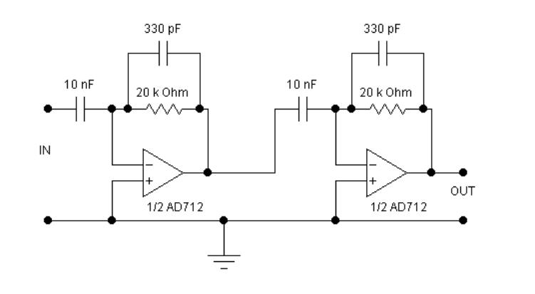
The circuits examined thus far rely on linear feedback for their operation. The magnitude of the signal returned to the negative input is always strictly proportional to the output voltage. Consequently, within the limits defined by the operational amplifier...
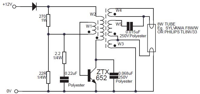
This circuit is an 8W inverter designed to drive an 8W fluorescent lamp from a 12V power supply, utilizing an inexpensive inverter based on a ZTX652 transistor. The inverter operates from power supplies ranging from 10V to 16.5V, achieving...
This is a battery charger circuit that has the advantage of automatically disconnecting the battery when charging is complete. The voltage sensor used in this circuit is the LM301 IC, which serves to disconnect the battery when the charging...
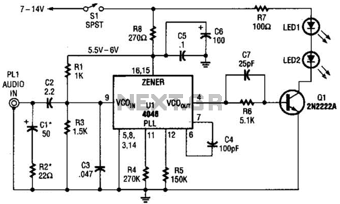
The transmitter for the wireless headphones is constructed using a CD4046 CMOS phase-locked loop, which is paired with a driver transistor and a set of infrared LEDs. While the CD4046 contains two phase comparators, a voltage-controlled oscillator (VCO), a...
This LED flasher circuit is a classic two-transistor flip-flop. It is a popular circuit often built by beginners in the electronics hobby. The schematic diagram of this well-known LED flasher circuit includes two transistors, two capacitors, four resistors, and...
The most important part of this 88-108 transmitter is the Colpitts oscillator. Capacitors C3, C4, C5, C6, diodes CD1 and CD2, and inductor L1 determine the transmission frequency. The RF oscillator... The Colpitts oscillator is a type of electronic oscillator...