
Connecting an IR Sensor

The described circuit integrates IR LEDs and receivers with an Arduino microcontroller for applications such as remote control systems or obstacle detection. The circuit begins with the power supply, where the +5V from the Arduino is connected to the positive terminals of the IR receivers, providing the necessary operating voltage. The ground connections are crucial for establishing a common reference point, which is achieved by linking the ground pins of the IR receivers to the Arduino's GND.
The signal output from the IR receivers is routed through 220-ohm resistors to prevent excessive current that could damage the Arduino's input pins. The choice of 220 ohms is a standard value that balances current flow while ensuring reliable signal detection. The right receiver's output is directed to pin 7, while the left receiver's output is assigned to pin 8, allowing the Arduino to differentiate between signals from each receiver.
The IR LEDs are configured to emit infrared light when activated. Their anodes are connected through 2k-ohm resistors to port 9 of the Arduino. This resistor value is chosen to limit the current flowing through the LEDs, ensuring they operate within safe parameters while providing sufficient brightness for effective operation.
To validate the wiring and functionality of the circuit, the use of a virtual breadboard is recommended. This simulation tool allows for real-time observation of connections and helps identify any errors in the wiring before physical assembly. Proper verification of all connections ensures the circuit operates as intended, minimizing troubleshooting and enhancing reliability in the overall design.The last thing to do is to wire the IR LEDs, the resistors, and the IR receivers into the Arduino. First, connect the +5v prongs of the IR receivers (right prong if facing the receiver) using the red wires. They should be directly hooked up to the +5 volt port on the Arduino with no resistor in series. Next, connect the Ground prongs of the IR rec eivers (middle prong), which should be on the same bus as the IR LEDs` cathode, to the GND port of the Arduino using the black wires. The third prongs, or signal prongs, of the IR receivers (left prong if facing the receiver) should be connected through the 220 ohm resistors to the Arduino`s pins 7 and 8 (right receiver on pin 7, left receiver on pin 8) using the grey wires.
Finally, the anode of the IR LED`s should be run through separate 2k resistors into port 9 using the yellow wires. Check the virtual breadboard to ensure each wire is hooked up correctly. 🔗 External reference
Related Circuits
A 2002 Blazer was diagnosed with error codes P0155 and P0756, indicating a malfunction in the O2 sensor heater circuit and a performance issue with the shift solenoid B circuit. The vehicle initially has power, but it loses power...
Q1, Q2, and Q3 form a high-impedance super-Darlington configuration that drives the relay, amplifying the 50 or 60 Hz alternating mains supply frequency induced in the sensor by the human body. Capacitors C1, D2, and D3 ensure clean switching...
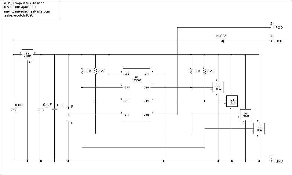
Just a handful of components builds an 8-pin microcontroller based circuit for temperature logging via a serial port; small, fast, and acceptably accurate. More: provides real-time data to your computer via serial port, interfaces up to four DS1820 temperature...
Detecting the color of an object can be an interesting and useful electronic application. This can be achieved using a color sensor like the TCS3200 in conjunction with a general-purpose microcontroller such as the AVR ATmega32. The TCS3200 chip...
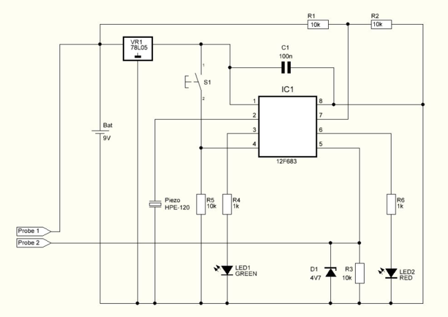
The water detection time is less than 10 seconds. Since the microcontroller enters a low consumption state between readings to preserve battery life, this state is always 10 seconds long. If water reaches the probes while being in the...

The CCD camera sensor is a very useful device that is compact in size while providing excellent quality. It can be easily installed with a television through the video input terminals, allowing for the transmission of modulated video signals...