
Tremolo Circuit

The circuit operates by leveraging a phase-shift oscillator (U1C) that produces a low-frequency oscillation. This oscillator typically consists of an operational amplifier configured in a feedback loop that introduces phase shifts to create a sine wave output at a frequency in the range of a few Hertz. The output of U1C is fed to transistor Q1, which acts as a modulator. The modulation of the gain of U1D is achieved by varying the control voltage applied to its input, influenced by the oscillating signal from Q1.
Resistor R11 plays a critical role in controlling the depth of the modulation effect. By adjusting R11, the user can increase or decrease the amplitude of the modulation signal, thus altering how pronounced the VLF AM effect is on the audio signal. A higher resistance value will result in a subtler effect, while a lower value will yield a more pronounced modulation.
Resistor R12 is responsible for adjusting the frequency of the modulation effect. Changing the resistance value alters the feedback network of the phase-shift oscillator, which in turn modifies the frequency of the oscillation. This allows for a range of modulation frequencies to be selected, enabling the user to tailor the sound to their preferences.
Overall, this circuit design is beneficial for musicians and sound designers looking to incorporate unique modulation effects into their audio signals, enhancing the sonic characteristics of their instruments or audio production. Proper implementation of the circuit components and careful tuning of R11 and R12 can yield a wide variety of creative sound effects. This circuit adds a VLF AM component to an audio signal. This effect is widely used in musical instruments. U1C, a phase-sh ift oscillator operating at a few Hz applies a signal to Ql, which modulates the gain of U1D. Rll varies the level of the effect, while R12 varies the frequency.
Related Circuits
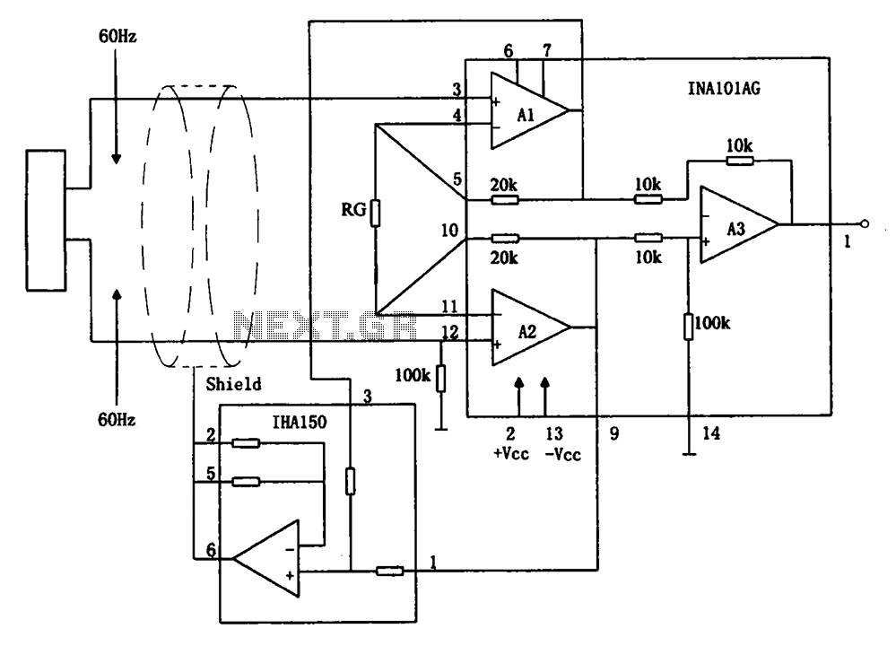
The circuit diagram illustrates a hum elimination instrument amplifier circuit. The amplifier stages A1 and A2 utilize the integrated operational amplifier INA101, followed by stage A3 which employs the INA105. A feedback circuit is incorporated to reduce the power...
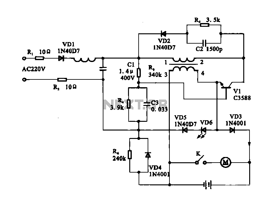
The circuit operates as a light-activated switch that controls white moving lights. It features high sensitivity, stable performance, and good anti-interference characteristics. A photosensitive resistor (RI) is employed to detect ambient light levels. During the day, the resistor exhibits...
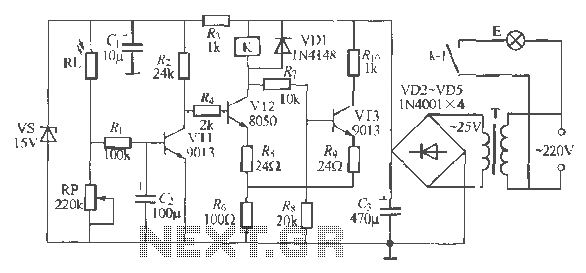
Electric shaver motor drive circuit. It illustrates a typical motor drive circuit for an electric shaver. AC 220V is used to charge the battery through the charging circuit, which also provides power to the motor. After activating the charge-on...
This circuit is a simple analog multiplier. The operation of the circuit can be understood by considering A2 as a controlled gain amplifier that amplifies V2, with its gain dependent on the ratio of the resistance of PC2 to...
This FET audio mixer exemplifies the versatility of Field Effect Transistors (FETs). Although FETs were originally designed for high-frequency applications, they are also highly effective in audio frequency applications. The circuit can accommodate an unlimited number of inputs, provided...
The PCA84C-440/441 is a single-chip microcomputer integrated circuit produced by Philips. It is widely utilized in both domestic and imported large screen color televisions, including those manufactured by Philips and other brands. The PCA84C-440/441 IC is housed in a...