
Mains Slave Switcher

The slave switch circuit is designed to enhance the convenience and safety of operating multiple electronic devices simultaneously. By using the electric field generated by a lamp, this system eliminates the need for direct modifications to the devices involved. The three-stage amplifier plays a crucial role in amplifying the signal from the sensing wire, ensuring that even small changes in current draw can be detected and used to control the relay. The relay, once activated, can handle the power requirements of the connected devices, providing a seamless transition from the master unit to the slave units.
The use of a capacitor mains dropper allows for efficient power management, ensuring that the relay can be powered without generating excessive heat, which is critical for maintaining the longevity and reliability of the circuit. The design requires careful consideration of safety standards, as it operates directly with mains voltage. Therefore, all components should be rated appropriately for the voltage and current they will handle, and the entire assembly must be housed in a robust enclosure to prevent accidental contact with live parts.
By incorporating adjustable sensitivity through the emitter resistor, users can tailor the circuit to their specific needs, accommodating variations in the electrical characteristics of different lamps or devices. The requirement to wrap the sensing wire around the lamp lead post-switch is a vital detail that ensures the circuit only activates when the lamp is indeed powered, preventing false activations.
Overall, this slave switch circuit provides a practical solution for managing multiple devices on a workbench or in similar environments, enhancing user experience while prioritizing safety and efficiency.There are many situations where two or more pieces of equipment are used together and to avoid having to switch each item on separately or risk the possibility of leaving one of them on when switching the rest off, a slave switch is often used. Applications which spring to mind are a computer/printer/scanner etc or audio amplifier/record deck/tune
r combinations or perhaps closest to every electronics enthusiast`s heart, the work bench where a bench power supply/oscilloscope/soldering iron etc are often required simultaneously. The last is perhaps a particularly good example as the soldering iron, often having no power indicator, is invariably left on after all the other items have been switched off.
Obviously the simplest solution is to plug all of the items into one extension socket and switch this on and off at the mains socket but this is not always very convenient as the switch may be difficult to reach often being behind or under the work bench. Slave switches normally sense the current drawn from the mains supply when the master unit is switched on by detecting the resulting voltage across a series resistor and switching on a relay to power the slave unit(s).
This means that the Live or Neutral feed must be broken to allow the resistor to be inserted. This circuit, which is intended for switching power to a work bench when the bench light is switched on, avoids resistors or any modifications to the lamp or slave appliances by sensing the electric field around the lamp cable when this is switched on. The lamp then also functions as a power on` indicator (albeit a very large one that cannot be ignored) that shows when all of the equipment on the bench is switched on.
The field, which appears around the lamp cable when the mains is connected, can be sensed by a short piece of insulated wire simply wrapped around it and this is amplified by the three stage amplifier which can be regarded as a single super-transistor with a very high gain. The extremely small a. c. base current results in an appreciable collector current which after smoothing (by C3) is used to switch on a relay to power the other sockets.
Power for the relay is obtained from a capacitor mains dropper` that generates no heat and provides a d. c. supply of around 15 volts when the relay is off. The output current of this supply is limited so that the voltage drops substantially when the relay pulls in but since relays require more current to operate them than they do to remain energized, this is not a problem.
Since the transistor emitter is referenced to mains Neutral, it is the field around the mains Live which will be detected. Consequently, for correct operation the Live wire to the lamp must be switched and this will no doubt be the case in all lamps where the switch is factory fitted.
In case of uncertainty, a double-pole switch to interrupt both the Live and Neutral should be used. The sensitivity of the circuit can be increased or decreased as required by altering the value of the T2 emitter resistor. The sensing wire must of course be wrapped around a section of the lamp lead after the switch otherwise the relay will remain energized even when the lamp has been switched off.
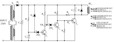
The drawing shows the general idea with the circuit built into the extension socket although, depending on the space available an auxiliary plastic box may need to be used. The circuit itself is not isolated from the mains supply so that great care should be taken in its construction and testing.
The sensor wire must also be adequately insulated and the circuit enclosed in a box to make it inaccessible to fingers etc. when it is in use. 🔗 External reference
Related Circuits

This circuit was designed to control power delivery to a Peltier cooler in a vehicle. The power to the load from the vehicle's battery is managed by a Single Pole Double Throw (SPDT) relay. The circuit utilizes an SPDT relay...
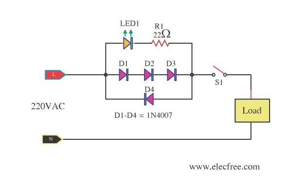
A need exists for a 220V AC line light display or main voltage monitor due to frequent electrical issues in a home. To create a 220V AC line light display or voltage monitor, a circuit can be designed using a...

A circuit that will find enough applications. Basically, the designing became in order to exist delay in quench one or more lamps in a stairwell or in any other space exists this need. It can become use for the...
The following circuit illustrates a Mains Remote-Alert Circuit Diagram. Features include simple circuitry, with the transmitted signal being conveyed effectively. The Mains Remote-Alert Circuit is designed to provide a notification system that alerts users about the status of mains power....
This very simple circuit acts as a high sensitivity capacitive sensor. Lamps and/or Buzzers are operated at half the mains supply voltage when a part of the human body comes in contact with the sensor or approaches it at...
Due to the energy crisis, load shedding has become a common issue in several countries. Sudden power fluctuations, surges, and high voltage can damage sensitive household appliances such as TVs, VCRs, VCPs, and music systems. This circuit offers protection...