
The VGA Test Box Circuit

The circuit design centers around the integration of the PIC Microcontroller, which is the core component responsible for executing programmed tasks. The power circuit is simplified with a 9V battery providing the necessary voltage input to the LM7805 voltage regulator, which outputs a regulated 5V DC. The inclusion of a 1µF capacitor on the output helps to filter any voltage fluctuations, ensuring stable operation of the microcontroller and connected components.
The input mechanism utilizes SPST buttons that are connected to ground. When a button is pressed, it creates a path to ground for the corresponding I/O pin, allowing the microcontroller to register the input. The use of pull-up resistors (4.7kΩ or 10kΩ) ensures that the I/O pin remains at a high logic level when the button is not pressed, preventing unwanted short circuits and ensuring reliable signal integrity.
The SPTT switch, while optional, introduces versatility by allowing the selection between three output options, suitable for applications requiring color selection in a display system. The connection from the PIC to the CRT's RGB inputs can be made directly, with the selected color determined by the active connection. This method provides a straightforward approach to controlling the display output based on user interaction through the switch.
Pin 1 serves a critical role in system management as the reset pin. When the pin is held low, the microcontroller resets, clearing its memory and restarting its operation. For continuous operation without manual intervention, this pin is tied high, ensuring that the microcontroller remains active as long as it is powered. This design choice streamlines the circuit by eliminating the need for a physical reset button while maintaining the functionality required for the project. Overall, the schematic emphasizes simplicity and efficiency, making it accessible for users with varying levels of experience in electronics.There are actually very few electronic components necessary for this project as the PIC Microcontroller is the powerhouse doing most the work. The few components necessary like, buttons, switches & power circuit are trivial forms of I/O which makes understanding how the project works eveneasier.
The power circuit is just a 9v Battery hooked up to the LM7805 with a 1uF capacitor hooked to output & ground of the LM7805 to keep a steady 5v DC. The SPST buttons are tied to ground so when the button is pushed the I/O pin it is attached to is effectively tied to ground. To avoid having a short circuit when the button is pushed, 4. 7K © or 10K © pull-up resistors are used. The SPTT Switch is a non-standard 3 way switch. It can be substituted with any other type of button(s) or switch(es) that will allow 1 input to go to one of 3 outputs.
It is optional but you can just tie the wire directly from the PIC to one of the the CRT R/G/B inputs. It`s just a matter of which color will display, Red, Green or Blue. This is tied high (logic 1; +5v) once again using a pull-up resistor. Pin 1 is effectively a reset pin. The PIC will restart-Memory Clear-when this pin is low (logic 0, +0v). For this project I did not include a reset button so I just have the pin tied high always, so the PIC will always be running as long as it is powered.
🔗 External reference
Related Circuits
1. Abstract Wet-garden is an interactive flower garden and an ambient indoor sculpture. When people walk around it, it changes motion and LED blinking speed. Wet-design is designed for everyone who wants a tangible interaction object and an interesting...

The circuit consists of a series of dual power supplies, providing a symmetrical ±15V supply for linear circuits. The same principle is applicable to non-symmetrical supplies, such as 5.0V and -12V regulators, which are used in applications like registers....
This is an electronic muscle stimulator circuit that stimulates the nerves in the area of the body where electrodes are attached. It is useful for relieving pain. The electronic muscle stimulator circuit operates by delivering electrical impulses through electrodes placed...
Also known as a megger insulation resistance meter, this device measures resistance at the megohm level. It is primarily used to assess the insulation resistance of motors, electrical circuits, and equipment. Additionally, it helps determine whether there is circuit...
Long-distance infrared transmitter circuit diagram. This simple circuit offers a considerable range by utilizing three infrared transmitting LEDs (IR1 through IR3) in series to enhance the radiated power. To further improve directivity and power density, the IR LEDs can...
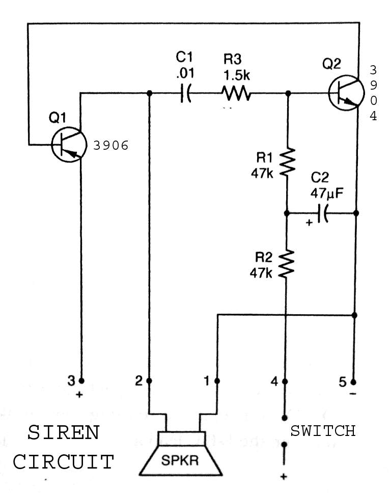
3904 3906 Siren Circuit. The circuit generates a wailing siren sound when the switch is activated. The 3904 3906 Siren Circuit is designed to produce a distinctive wailing sound, commonly used in alarm systems and signaling devices. The circuit utilizes...