
make this 1kva 1000 watts pure sine
The described circuit operates as a high-efficiency inverter, utilizing MOSFET technology to amplify input signals and convert them into a usable AC output. The differential amplifier stage formed by Q1 and Q2 is crucial for ensuring that the input sine wave is accurately amplified without introducing significant distortion. This stage's role is to maintain signal integrity while preparing it for the driver stage.
The driver stage, consisting of Q3, Q4, and Q5, is responsible for managing the power delivery to the transformer. The push-pull configuration of the MOSFETs allows for efficient switching, effectively alternating the voltage across the transformer windings. This method ensures that the transformer operates at its optimal efficiency, generating the required 1 kVA output while minimizing energy losses.
The sine wave generator circuit is fundamental to the operation of the inverter. By employing operational amplifiers and passive components, it generates a sine wave that serves as the input for the amplifier stage. Operating within a voltage range of 5 to 12 volts, this generator is powered by the same batteries that supply the inverter. However, the exponential nature of the sine wave output can lead to thermal challenges for the MOSFETs, necessitating careful thermal management strategies.
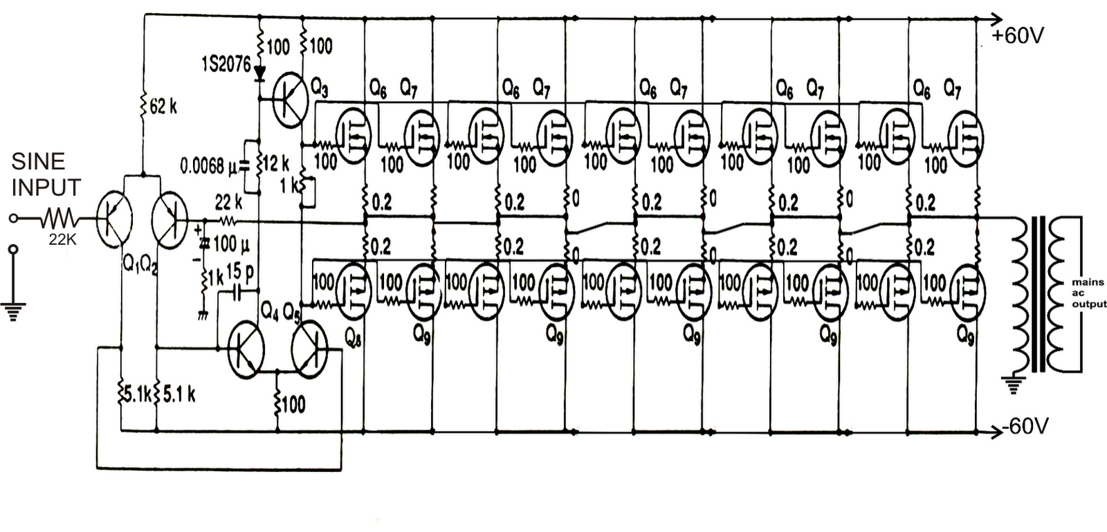
To mitigate heating concerns and enhance performance, a PWM-based approach is recommended. This alternative method allows for the generation of pulses that more closely mimic a sine wave, reducing the risk of excessive heating and improving the overall efficiency of the inverter circuit. By optimizing the PWM signal, the circuit can maintain the desired output characteristics while ensuring the reliability of the MOSFETs during operation. This comprehensive design approach ultimately results in a robust and efficient inverter capable of delivering high-quality AC power.As can be seen in the first diagram below, the configuration is a simple mosfet based designed for amplifying current at +/-60 volts such that the connected transformer corresponds to generate the required 1kva output. Q1, Q2 forms the initial differential amplifier stage which appropriately raises the 1vpp sine signal at its input to a level
which becomes suitable for initiating the driver stage made up of Q3, Q4, Q5. The mosfets are also formed in the push pull format, which effectively shuffles the entire 60 volts across the transformer windings 50 times per second such that the output of the transformer generates the intended 1000 watts AC at the mains level. For acquiring the intended pure sine wave output, a suitable sine input is required which is fulfilled with the help of a simple sine wave generator circuit.
It is made up of a couple of opamps and a few other passive parts. It must be operated with voltages between 5 and 12. This voltage should be suitably derived from one of the batteries which are being incorporated for driving the inverter circuit. The below given diagram shows a simple sine wave generator circuit which may be used for driving the above inverter circuit, however since the output from this generator is exponential by nature, might cause a lot of heating of the mosfets.
A better option would be to incorporate a PWM based circuit which would supply the above circuit with appropriately optimized PWM pulses equivalent to a standard sine signal. 🔗 External reference
Related Circuits

A Wien-bridge oscillator can be made variable by utilizing two frequency-determining components that are adjusted simultaneously with high tracking accuracy. However, high-quality tracking potentiometers or variable capacitors are often costly and challenging to procure. To circumvent the need for...
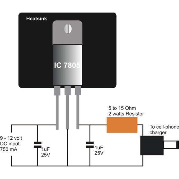
Construct a straightforward DC to DC mobile battery charger to charge your mobile phone battery at any time and location by connecting it to a 12-volt source from a car or motorbike battery. This mobile battery charger circuit is designed...

A VU meter, or volume unit meter, is a device used to indicate the music volume output from an amplifier or loudspeaker system. It can also be viewed as a device for displaying the PMPO (Peak Music Power Output)...
An inverter is introduced which primarily utilizes a MOS field-effect transistor in conjunction with a conventional power transformer. The output power of the inverter is determined by the specifications of both the MOS field-effect transistor and the transformer, thereby...
The two circuits below illustrate the generation of low-frequency sine waves by shifting the phase of the signal through an RC network, ensuring that oscillation occurs when the total phase shift reaches 360 degrees. The transistor circuit on the...

The following article outlines a sophisticated LED sequencing and diverging ring light that can serve as a tail brake light in vehicles. This circuit concept was proposed by a dedicated reader, Mr. Bobby. The design aims to create a...