
make yourself a d c mobile charger

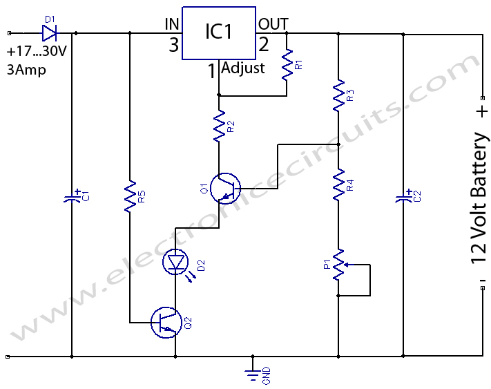
This mobile battery charger circuit is designed to convert a 12V DC input from a vehicle battery into a suitable voltage for charging mobile devices. The core of the circuit typically consists of a voltage regulator, such as the LM7805, which steps down the 12V input to a stable 5V output, ideal for most mobile phone batteries.
The circuit begins with a fuse connected in series to the 12V input to protect against overcurrent. Following the fuse, a capacitor is placed to filter out any voltage spikes and provide a smoother input to the voltage regulator. The LM7805 voltage regulator is then connected, with its input pin receiving the filtered 12V, while the output pin provides a regulated 5V output.
To ensure stability and transient response, additional capacitors are placed at the output side of the regulator. These capacitors help to maintain the output voltage during load changes and improve the overall performance of the circuit.
A diode may also be included at the output to prevent reverse current flow, which could potentially damage the mobile device being charged. The output can be connected to a USB port, allowing for easy connection to various mobile devices.
For enhanced functionality, an LED indicator can be incorporated into the circuit to indicate when the charger is active. This can be connected in parallel with the output, with an appropriate resistor to limit current through the LED.
This simple yet effective design provides a reliable solution for mobile phone charging on the go, utilizing readily available components and requiring minimal assembly skills. The circuit's compact size allows it to be easily integrated into various portable applications, making it a versatile tool for mobile device users.Make yourself this simple dc to dc mobile battery charger and charge your mobile phone battery whenever and wherever you want, simply by connecting it to a 12 volt source from your car or motorbike battery.. 🔗 External reference
Related Circuits
This project is one for the experimenter, but as shown will work extremely well. The sensing circuit can be made so sensitive that a load of only 2.5mA is enough for the circuit to detect, and disconnect the charger....
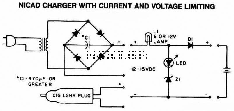
The following diagram is the schematic of a Ni-CAD battery charger circuit, which includes current and voltage limiting features to extend the battery's lifespan. The lamp L1 will illuminate brightly, and the LED will be off when the battery...
12 Volts Lead Acid Battery Charger Circuit. Apart from serving as a standard battery charger, this circuit is ideal for providing a constant charge to a 12-Volt lead-acid battery. This 12-Volt lead-acid battery charger circuit is designed to efficiently charge...
A constant-current/constant-voltage linear charger for single-cell lithium-ion (Li-ion) batteries can be constructed using the EUP8054 battery charger controller chip and a few passive components. This compact integrated circuit is suitable for various portable devices and is compatible with USB...
The following circuit illustrates a simple battery charger equipped with a temperature sensor. This circuit is based on the LM350 integrated circuit. Features include negative... The circuit utilizes the LM350 voltage regulator IC, which is known for its ability to...

Consumers of mobile wireless devices expect a functional balance between performance and battery life. This expectation is especially relevant in third-generation (3G) wireless designs, as these devices feature more powerful and multimedia-rich capabilities. While processor performance (Moore's Law) doubles...