
Make this Fancy LED Tail Ring Light Circuit for your Car

The circuit design features a serial shift register (IC1), which is pivotal for controlling the LED sequencing. The shift register operates by receiving clock pulses at pin #8, which triggers the output pins sequentially. Each activated output pin corresponds to an LED that is part of the circular arrangement. The LEDs are driven by transistors (T1, T2, T3, T4, T5), which act as switches, allowing current to flow through the LEDs when activated. The arrangement of the LEDs in a circular pattern enhances the visual effect of the light sequence, creating a dynamic and engaging display as the brake is applied.
The design can be further refined by incorporating additional features such as adjustable LED brightness, using PWM (Pulse Width Modulation) techniques, to enhance visibility during different lighting conditions. Additionally, integrating a microcontroller could allow for customizable lighting patterns and sequences, providing greater flexibility and functionality. The power supply for the circuit should be carefully considered to ensure it meets the voltage and current requirements of the LEDs while maintaining efficiency and reliability.
In summary, this LED sequencing diverging ring light circuit offers a creative solution for automotive lighting, combining aesthetics with functionality. The careful arrangement of components and thoughtful design choices contribute to an effective and visually striking tail light system.The following article describes a fancy LED sequencing/diverging ring type light which can be used as a tail brake light in cars. The circuit idea was requested by one of the avid readers of this blog, Mr. Bobby. lets learn more. Could this circuit be adapted to create a round tail light that lights rings in sequence from the center out as the bra
ke is pressed, one ring at a time until all the LEDs are lit and then flash all the LEDs twice and keep all LEDs lit solid after If not, could you design a circuit that would I would be willing to pay for your time. IC1 which is a "serial shift resistor" forms the heart of the entire circuit, the main function of this IC is to illuminate the LEDs connected to pin outs #3-4-5-6-10-11-12-13 in a sequence, keeping the sequence latched and illuminated as it proceeds.
This happens in response to each clock pulse applied at pin#8 of the IC. The LEDs which aretriggeredby the pin#3-4-5-6 and 10 are arranged as rings such that it illuminates from inner most ring first toward the outermost ring, producing an interesting and visually rich effect. In response to the above clocks, the sequence proceeds creating the desired diverging illumination effects, until it reaches pin#10.
The LEDs receive the required positive supply through T1 which stays triggered due to the low logic at pin#13 of IC1 The LEDs which needs to be connected across the collectors of T1 and T2/T3/T4/T5 may be wired up in the following manner. The arrangement should be designed in a circular manner to form the corresponding RINGs. 🔗 External reference
Related Circuits

This three-band equalizer circuit is an active filter network designed for bass, midrange, and high audio frequencies. It utilizes the LM833 operational amplifier from National Semiconductors. The output of this three-way graphic equalizer is intended to be DC coupled;...
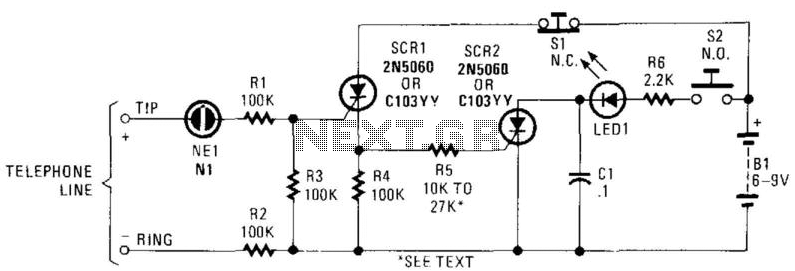
In this circuit, the ringing voltage on a telephone line causes NE-1 to break over, triggering SCR1, which in turn triggers SCR2. If a call has been received, depressing S2 will cause LED1 to light. Depressing S1 resets the...

This circuit utilizes two operational amplifiers (op-amps) to create a unique sound effect. The first op-amp, CA741, is configured as a standard astable multivibrator, generating timing pulses controlled by components C1, R2, and variable resistor VR1. The output from...
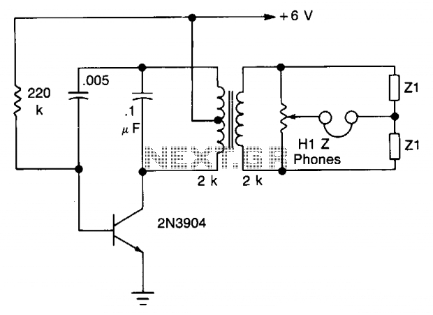
The transistor is configured as an audio oscillator, utilizing an audio transformer in the collector. The secondary winding is connected to a linear potentiometer. The ratio between the two sections of the potentiometer from the slider is proportional to...

The circuit depicted in Figure 3-49 illustrates an autotransformer that is controlled by a time relay (KT). The delay time set by the KT relay corresponds to the motor's startup duration. The circuit utilizes an autotransformer, which is a type...
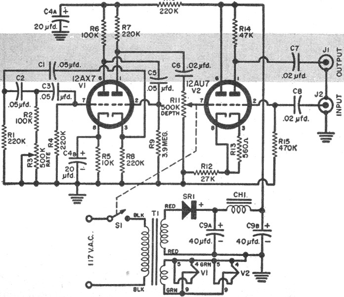
RF Cafe visitor Jim L. requested that this "Build Your Own Vibrato" article from the December 1957 edition of Popular Electronics be posted. The tagline states, "Make like Elvis with an electronic throbbing guitar." Vibrato, for those unfamiliar with...