
Inverter Circuit For Soldering Iron circuit

The inverter circuit operates by converting a DC voltage into an AC output suitable for powering low-wattage devices such as soldering irons. The astable multivibrator configuration formed by Q1 and Q2 is crucial as it establishes the frequency of the output signal. The frequency of 50Hz is standard for many applications, particularly in regions where the mains supply frequency is aligned with this value.
The output from the astable multivibrator is a square wave, which is then amplified by the Darlington pairs Q3-Q5 and Q4-Q6. The Darlington configuration is advantageous due to its high current gain, allowing the circuit to drive higher loads without requiring excessive base current. This characteristic is particularly important for applications that demand higher power outputs from low-power input signals.
In this design, Q3 and Q4 serve as the driver transistors, while Q5 and Q6 provide additional amplification. The use of BC558 and BD140 transistors in the Darlington pair configuration ensures that the output stage can handle the necessary current to power the soldering iron effectively. The circuit is completed with passive components such as resistors and capacitors, which stabilize the operation and filter the output signal.
Overall, this inverter circuit is an efficient solution for providing AC power in situations where conventional mains electricity is unavailable, making it a practical tool for hobbyists and professionals needing a portable soldering solution. Proper attention to component ratings and thermal management is advisable to ensure reliable operation, especially when driving devices with varying power demands.Here is a simple but inexpensive inverter for using a small soldering iron (25W, 35W, etc) In the absence of mains supply. It uses eight transistors and a few resistors and capacitors. Transistors Q1 and Q2 (each BC547) form an astable multivibrator that produces 50Hz signal. The complementary outputs from the collectors of transistors Q1 and Q2 are fed to pnp Darlington driver stages formed by transistor pairs Q3-Q5 and Q4-Q6 (utilising BC558 and BD140)..
🔗 External reference
Related Circuits
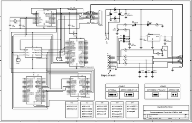
The ATMEL AVR programmer operates with the Windows program "Ponyprog," which is compatible with Windows 95, 98, and XP. The ATMEL AVR programmer is a device designed for programming AVR microcontrollers. It interfaces with the microcontroller through the ISP (In-System...
The circuit illustrated in Figure 3-81 employs a transistor delay circuit to facilitate start-stop cycle control. It can operate in both manual and automatic modes. The circuit is primarily governed by the motor run time circuit, which includes transistors...
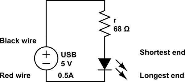
The LED operates at 3V, and based on information available online, a blue LED typically supports a maximum current of 0.03A. Given the available current from the USB source, the intention is to construct a parallel circuit. However, the...
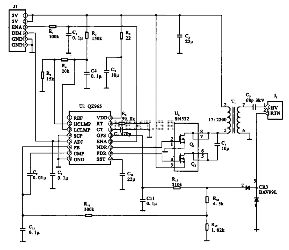
A typical liquid crystal display inverter circuit (OZ965) is primarily controlled by the OZ965 chip. It includes a driving field effect transistor (U2), a step-up transformer, the backlight socket, and associated circuitry. A 5V DC voltage is provided by...
Emergency lights, fuse/relay panel, fresh air blower switch, engine control module, ignition coil, console switch, power windows, ABS control unit, ABS hydraulic unit, instrument cluster, taillight, headlight switch, automatic solenoid, ignition switch. The described circuit encompasses multiple essential components for...
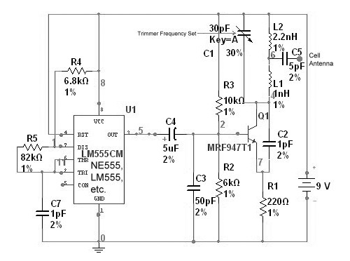
The circuit is based on the NE555 timer, functioning as a simple noise maker, with its output connected to a single transistor oscillator. This oscillator is designed to operate within a frequency range of 800 MHz to 2 GHz,...