
make your own portable Guitar Amp

The construction of a portable guitar amplifier involves several key components, including a power supply, amplifier circuitry, and a speaker. The power supply typically consists of a rechargeable battery, which provides the necessary voltage and current for the amplifier circuit. The ammeter is used to monitor the current flowing from the charger to the battery, ensuring that the battery is charged correctly without exceeding its rated capacity.
The amplifier circuit can be built using operational amplifiers or dedicated audio amplifier ICs, which are designed to boost the audio signal from the guitar. The circuit should include capacitors for filtering and stabilizing the power supply, as well as resistors to set gain levels and prevent distortion. It is crucial to design the circuit layout to minimize noise and interference, which can significantly affect audio quality.
The speaker selection is vital for the performance of the amplifier. An 8-ohm speaker rated for 3 watts is suitable for a portable application, as it can deliver adequate sound levels without requiring excessive power. The physical dimensions of the speaker should also be considered to ensure it fits within the enclosure of the portable amplifier.
Heat management is another critical aspect of the design. The heat sinks should be strategically placed near components that generate significant heat, such as the amplifier IC. Proper thermal management will enhance the reliability and longevity of the amplifier. Additionally, using thermal adhesive ensures a secure attachment of the heat sinks, allowing for efficient heat transfer away from sensitive components.
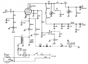
Finally, the enclosure of the amplifier should be designed to protect the internal components while allowing for adequate ventilation. Materials such as wood or plastic can be used to construct a lightweight yet sturdy enclosure. The design should also consider accessibility for controls and connections, such as input jacks for the guitar and output connections for headphones or external speakers. Overall, careful attention to detail in the circuit design, component selection, and enclosure will result in a functional and effective portable guitar amplifier.The guitar is a wonderful musical instrument which is capable of providing both melody and rhythm. However, every guitar player would have experienced the problem of low volume. The guitar is rarely heard unless the surroundings are absolutely quiet! To solve this problem, the guitar amp is often employed. If you have some knowledge in reading cir cuit diagrams, this tutorial will guide you to make your very own portable guitar amp. Estimated cost: The cost here depends entirely on what you will have to purchase, what you already have and what you manage to scavenge. Hence, it is totally variable. 8. Now built the circuit that is necessary. Instead of going into the details of explaining the circuit, we present the circuit diagram below. Follow it to the hilt. 9. Hook the positive end of the charger to one terminal of an ammeter. The other terminal is connected to the positive end of the battery. Connect the negative end of the battery with the negative end of the charger. Ans: The speaker that has been suggested here has a resistance of 8 ohms and can thus handle about 3 Watts of power.
It is also shallow in its depth and makes it possible to insert heat sinks. These specifications are important for the project and it would be better to stick to the above mentioned speaker unless you can obtain another one with the same specifications. Different speakers will also give different performances. Experiment at your own risk. Ans: Heat sinks help to dissipate the heat that is formed in the circuit. Too much heating can harm the circuit. The heat sinks used in this project are nothing but cut pieces of a regular heat sink that have been filed to fit in.
You can glue them using thermal glue that is available. 2. Be careful while using the hot glue and quick glue. These glues bond very strong and fast. Skin could easily get bonded by mistake and result in injuries. 🔗 External reference
Related Circuits
This simple circuit is designed to provide an output power of approximately 1 watt when connected to a 9-volt power supply. The key advantage of this circuit is its use of a dual Darlington configuration, which increases the input...
This circuit is a diagram of a mini amplifier. The amplifier circuit has a power output of 10 watts and is well-suited for car audio applications. It utilizes the TDA2009A integrated circuit as the power amplifier. To prevent excessive...
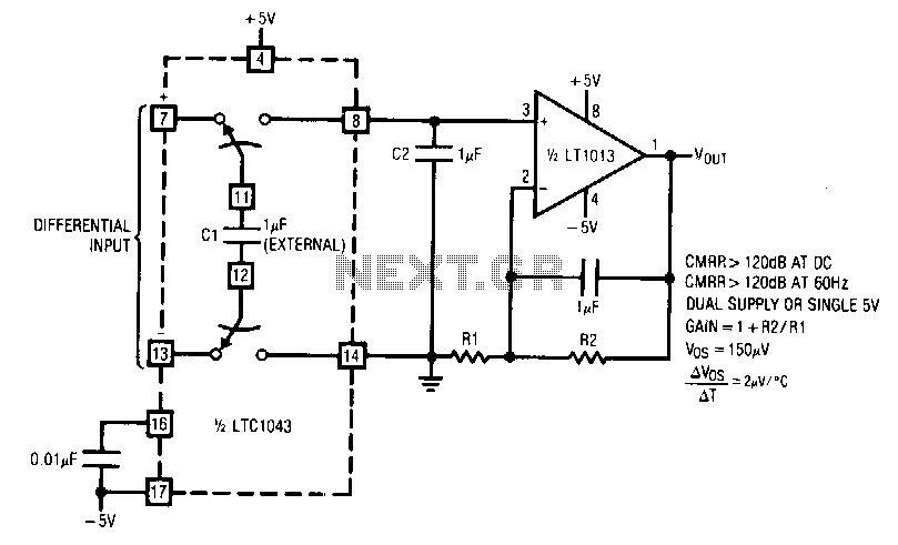
LTC1043 and LT1013 dual operational amplifiers are utilized to construct a dual instrumentation amplifier with only two packages. A single double-pole double-throw (DPDT) switch converts the differential input into a ground-referenced single-ended signal at the input of the LT1013....
China's national conditions indicate that the general living room area exceeds twenty square meters, often serving as a bedroom or listening room. For speakers with a sensitivity of 89 dB or higher, a pure Class A amplifier with a...
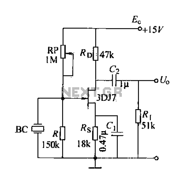
A field effect transistor (FET) voice amplifier has a low input impedance, approximately 1 kΩ, requiring the signal source to provide a constant current signal for operation. Unlike bipolar transistors, FETs are voltage-controlled devices that draw minimal current at...
1500 Watt RF Amplifier circuit can be utilized to drive a transmitter antenna. It is also applicable for powering RF high power sources, microwave heating, and other uses. The 1500 Watt RF Amplifier circuit is designed to amplify radio frequency signals,...