
Manual thermostat circuit

The adjustment potentiometer (RP) serves a crucial role in controlling the conduction angle of the TRIAC, which in turn regulates the power delivered to a load, such as a heating element. By varying the resistance of the potentiometer, the phase angle at which the TRIAC is triggered can be adjusted. This is essential for applications that require precise temperature control, such as in heating systems or temperature-sensitive processes.
In practical terms, the TRIAC is a semiconductor device that can conduct current in both directions when triggered. The conduction angle, defined as the portion of the AC cycle during which the TRIAC is active, determines the average power delivered to the load. A smaller conduction angle results in lower power output, while a larger angle increases the power delivered.
The potentiometer is typically connected in a phase control circuit, where it alters the timing of the TRIAC triggering. The circuit may include additional components such as resistors, capacitors, and diodes to shape the waveform and ensure stable operation. The adjustment of the potentiometer can be done manually, allowing for fine-tuning of the temperature output according to the requirements of the specific application.
In summary, the adjustment potentiometer RP is an integral component for achieving desired temperature control through the modification of the TRIAC conduction angle, providing versatility and precision in various electronic heating applications.Adjustment potentiometer RP, can change the TRIAC V conduction angle, to achieve tempering purposes.
Related Circuits
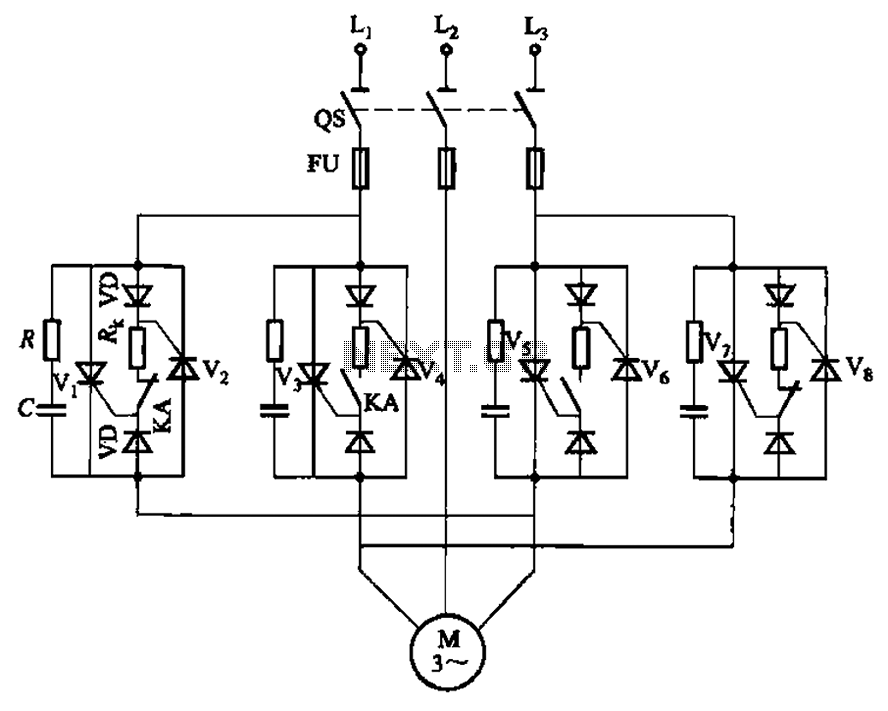
The circuit depicted in Figure 3-69 is designed for applications requiring frequent timing control for motor reversing operations. In this configuration, thyristors V1, V2, V7, and V5 are utilized for positive control of rotation, while thyristors V3, V4, and...
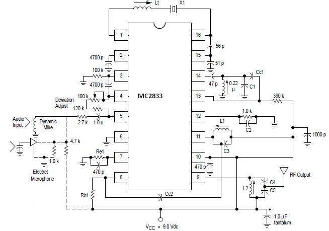
A simple FM transmitter circuit can be designed using the MC2833 integrated circuit, which is intended for cordless telephone and FM communication applications. This circuit includes a microphone amplifier, a voltage-controlled oscillator, and two auxiliary transistors. The final output...
Four observations regarding the Joule Thief AA battery LED circuit. The schematic of the LED circuit illustrates the power source (V1), which symbolizes a depleted battery with only 1 volt remaining and an internal resistance. The Joule Thief circuit is...
This is a subwoofer low-pass filter circuit, which is another variant based on the discharge from ST Microelectronics' TL062. The TL062 is a dual high-input impedance J-FET operational amplifier characterized by low power consumption and a high slew rate....
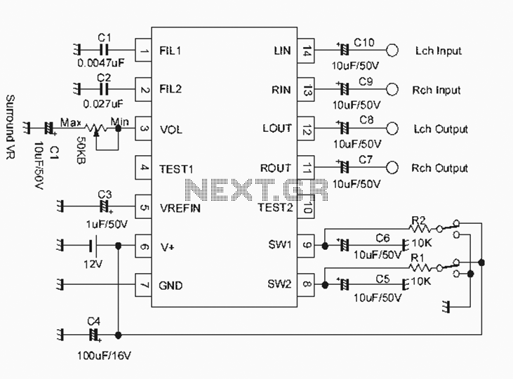
The NJM2701 3D surround sound audio processor integrated circuit can be designed into a very simple 3D surround sound system. The NJM2701 reproduces 3D surround sound using only two speakers and is suitable for various audio applications, including micro-components,...
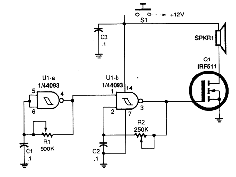
Gates U1-a and U1-b of the 4093 quad 2-input NAND Schmitt trigger are connected in variable, low-frequency square-wave oscillator circuits. The output of gate U1-a is connected to one of the inputs of gate U1-b. The square-wave output of...