
Thyristor controlled motor reversing circuit a timer

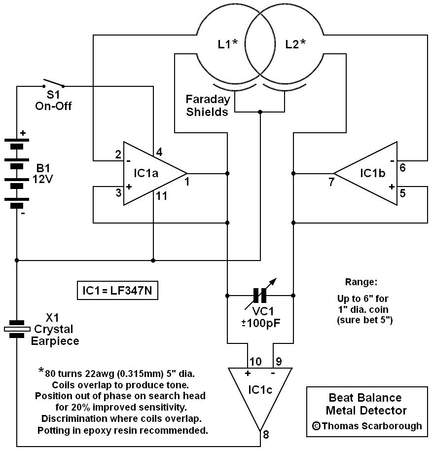
The circuit operates by utilizing a combination of thyristors and transistors to achieve precise control over the motor's operation. The thyristors V1, V2, V7, and V5 facilitate the positive rotation of the motor, enabling it to run in a forward direction. Conversely, thyristors V3, V4, and V6 manage the inversion control, allowing the motor to reverse its direction.
The role of transistor VT1 is critical as it acts as a switch that extends the timing for the motor's forward and reverse operations. This switching action is complemented by the delay circuit involving VT2, which further refines the timing control by introducing a delay before the motor changes direction. The resistors R and capacitors C serve as protective components, ensuring that the thyristors operate within safe limits and preventing potential damage due to overcurrent conditions.
Potentiometers RPi and RP2 provide an interface for users to adjust the timing settings. By varying the resistance in these potentiometers, the duration for which the motor runs in either direction can be modified, allowing for flexibility in applications where different timing requirements are necessary. This feature is particularly advantageous in automation systems where precise control over motor operations is essential for optimal performance.
Overall, this circuit exemplifies an effective design for controlling motor operations with an emphasis on timing and directional control, making it suitable for various industrial and automation applications. Circuit shown in Figure 3-69. It applies to require frequent timing control motor reversing operation of the occasion. Drawing, thyristor Vl, V2 and V7, vs used as a positive c ontrol rotation, V3, V4 and V5, V6 used inversion control; motor forward running and reverse running time, respectively, by the extension of single-junction transistor VTi and the like of the circuit configuration and the like by the VTz delay circuit to control; the resistor R and the capacitor C is used for the thyristor protection. Adjust potentiometer RPi and RPz, can change the motor running forward and reverse running time respectively.
Related Circuits
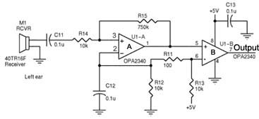
Assistance is required regarding the circuits provided below. The focus is on an ultrasonic receiver circuit that utilizes two ultrasonic components. The ultrasonic receiver circuit is designed to detect ultrasonic waves, typically in the frequency range of 20 kHz to...
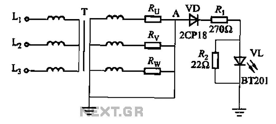
It is well understood that if the power transformer neutral line is disrupted, an unbalanced three-phase load can easily result in overvoltage conditions, potentially damaging electrical equipment such as household appliances and lamps. The neutral circuit alarm system is...
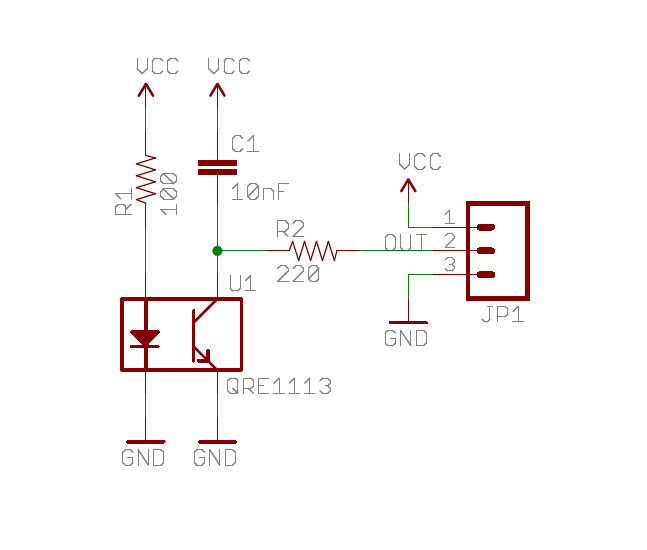
A real-time clock turns off the counter at night to conserve power. When a bee crosses under the LED, the light is reflected back to the sensor, which is a phototransistor, and triggers a digital input to the Arduino...
The following are LM555 timer circuits that have unusual functions. Designed to time a sports event; In this circuit the GREEN output is adjusted to be on for 3 minutes and then the RED output is set for 1...
A simple test circuit designed for troubleshooting audio and radio equipment. It can inject a square wave signal rich in harmonics or be used with headphones as an audio tracer. A single-pole double-throw switch is utilized to toggle between...
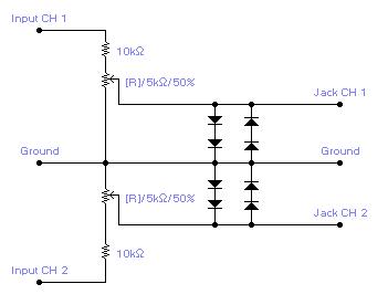
For simple electronic circuits, it may be sufficient to gain qualitative insights on dedicated electrical signals. This interface circuitry allows the line-in input of a standard PC sound card to be utilized as a 2-channel oscilloscope. Although this setup...