
Multi-output power supply circuit (MAX1902)
")
The multi-output power supply circuit based on the MAX1902 is engineered to efficiently manage power distribution within notebook computer systems. The MAX1902 is a highly integrated power management IC that facilitates the regulation of multiple output voltages from a single DC input, typically sourced from the laptop's battery. This capability is essential for powering various components on the motherboard, including the processor, memory, and peripheral devices.
The circuit configuration generally includes the MAX1902 chip, which controls the output voltages through a series of internal regulators. These regulators can be configured to provide different voltage levels, typically ranging from 1.2V to 3.3V, depending on the specific requirements of the components being powered. The device is capable of delivering up to 1A per output channel, ensuring sufficient current for high-performance applications.
Additionally, the circuit incorporates feedback mechanisms to maintain voltage stability across varying load conditions. This is achieved through the use of external resistors and capacitors that form a voltage divider and filter network, respectively. The feedback loop continuously monitors the output voltage and adjusts the duty cycle of the internal switching regulator to stabilize the output.
Protection features such as overcurrent protection, thermal shutdown, and under-voltage lockout are typically integrated into the design to enhance reliability and prevent damage to the components. The layout of the circuit board is also critical, as it must minimize noise and interference, which can affect the performance of sensitive electronic components.
In summary, the MAX1902-based multi-output power supply circuit is a sophisticated solution for managing power in notebook computers, providing reliable and adjustable DC voltage outputs necessary for modern computing demands.Multi-output power supply circuit (MAX1902) It shows the notebook computer motherboard power supply circuit which uses MAX1902 chip for power control circuit, which can be all the way in order to provide a DC voltage of the battery into a multi-channel DC voltage output.
Related Circuits
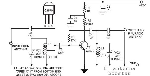
The input coil L1 is composed of four turns of 20 SWG enamelled copper wire, wound slightly spaced over a 5mm diameter former. It is tapped at the first turn from the ground lead side. Coil L2 is similar...
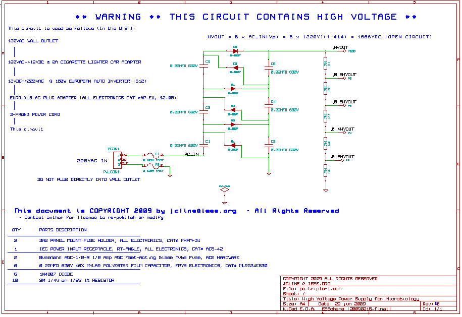
This high voltage, low current power supply has been designed for various experiments in systems and synthetic biology. The schematic and board layout are provided below. The circuit can output up to +1,866 VDC at under 1 mA and...
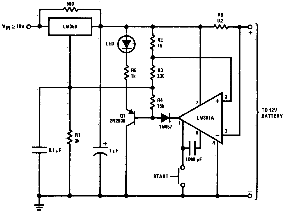
DC 12V Battery Charger Circuit Diagram. This circuit is a high-performance charger for gelled electrolyte lead-acid batteries. The DC 12V battery charger circuit is designed to efficiently charge gelled electrolyte lead-acid batteries, which are commonly used in various applications due...
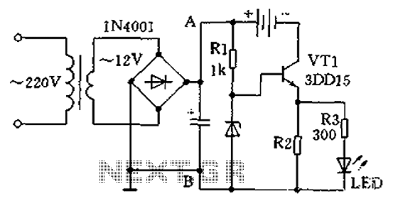
A practical single-tube constant current charger is illustrated, utilizing a transistor (VT1) that plays a crucial role in maintaining a constant current. The current value is determined by the voltage regulator and resistor R2. The general output voltage is...
The design of this project relies heavily on sensors, which are present in both the control module and the robot. The computer analyzes the signals from these sensors to determine appropriate output actions. The control unit utilizes potentiometers as...
The two circuits below illustrate using the 555 timer to close a relay for a predetermined amount of time by pressing a momentary N/O push button. The circuit on the left can be used for long time periods where...