
masthead preamp

The described circuit serves as an effective solution for enhancing signal strength in radio frequency applications. The preamplifier's wide bandwidth capability allows it to amplify signals across a significant range of frequencies, making it versatile for various communication needs. The incorporation of a relay enables the seamless transition between amplification and direct transmission, which is particularly useful for low-power transmitters.
The choice of the 2.2 mH chokes is critical, as their reactance must be sufficient to prevent signal loss at lower frequencies. The design allows for flexibility in construction, as users can customize the chokes based on their specific requirements. The use of a toroidal inductor minimizes electromagnetic interference, enhancing the overall performance of the circuit.
When designing the relay configuration, it is important to ensure that the coil resistance is adequate to prevent excessive current draw, which could lead to overheating or failure of the components. The two-pole changeover design offers the ability to switch between different circuit paths, optimizing the functionality of the preamplifier and transmitter.
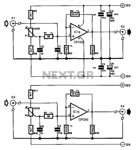
Safety precautions are essential, particularly regarding the application of DC power during transmission. Implementing a delay mechanism ensures that the preamplifier does not inadvertently activate during transmission, protecting sensitive components from damage. This circuit exemplifies a practical approach to integrating amplification and transmission capabilities in radio frequency applications, suitable for hobbyists and professionals alike.The first circuit is a simple preamplifier showing the power arangements for conveying DC to the amplifier via the coaxial cable. The second circuit is a small modification so the antenna can still be used for transmitting. The actual preamplifier in this circuit is a practical wideband amplfier that gives about 15 - 20dB of gain from 1.
8 MHz thro ugh to well over 200 MHz. You will no-doubt replace this circuit for your own favorite amplifier for the band you are interested in. The 2. 2mH chokes should have an absolute minimum reactance of 5000 ohms at the lowest frequency to be used.
For 145 MHz these may simply consist of a few turns of wire. I personally used a 10-turn 4mm Dia. coil in series with a 2. 2mH torroidal inductor. The relay should have a coil resistance in excess of 1000 ohms and have tw1o-pole changeover contacts. When I built this circuit I used tw1o 5v PCB mounting relays, each having a single pole changeover contact.
The relays each had a 560 ohm coil. If the DC power is switched OFF the preamplifier will become inactive and the relay will pypass the amplifier. In this manner it may be used with a low-power transmitter (typically up to 10 watts). My first switch was built inside the balun housing of a 2-metre beam antenna. Note that the DC 12 volts should NEVER be applied whilst transmitting or the poor little BFY91 will be blown to bits.
There is also a short delay betw1een removing the DC and the preamp dropping out into a safe condition for transmitting 🔗 External reference
Related Circuits
When the start switch is pushed, the output of the charger goes to 14.5 V. As the battery approaches full charge, the charging current decreases and the output voltage is reduced from 14.5V to about 12.5V, terminating the charging...
In many oscilloscopes, the most sensitive range is between 2 to 5 mV, although it is often possible to improve this to 1 to 2 mV by using a variable gain control. To achieve even better sensitivity, the current...
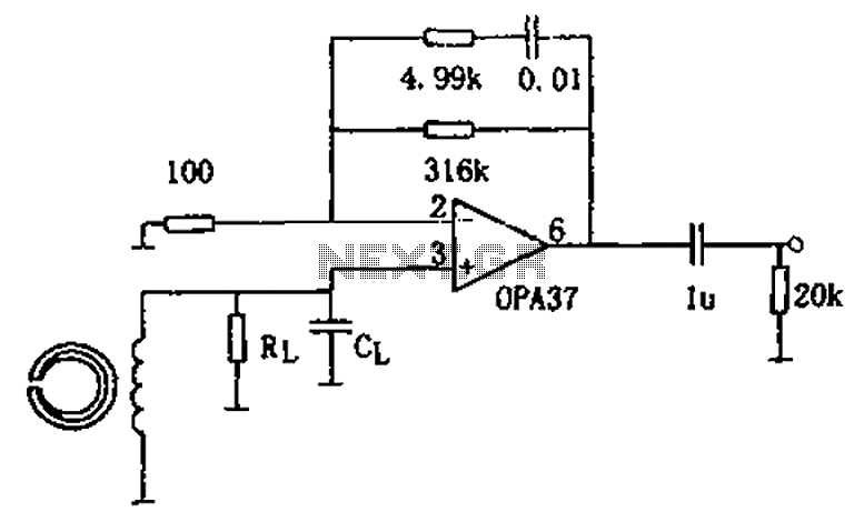
The circuit is a 90s common recorder head amplifier circuit that utilizes the ultra-low noise precision operational amplifier OPA37 as a preamplifier. This circuit is capable of providing standard NAB equalization. At a frequency of 1 kHz, it achieves...
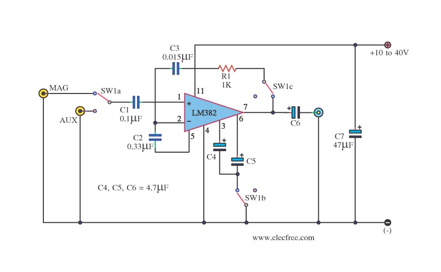
This is a simple preamplifier circuit. It can accept a general AUX sound signal as well as a signal from a microphone. The purpose of the circuit is to amplify the sound signal at the initial stage using an...

A similar circuit can be utilized with an 8-ohm speaker; in this instance, it should be placed in the position of the emitter resistor. This circuit functions as a replacement for a carbon microphone. The described circuit is intended for...
There is significant hiss produced by the circuit. Reducing the treble knob alleviates this issue, although it diminishes treble response. The hiss becomes more pronounced when the vibrato circuit is activated. After these observations, the board was re-capped according...