
VHF preamplifier with BFY91


If the DC power is switched OFF the preamplifier will become inactive and the relay will bypass the amplifier. In this manner, it may be used with a low-power transmitter (typically up to 10 watts). My first switch was built inside the balun housing of a 2-metre beam antenna.
Note that the DC 12 volts should NEVER be applied whilst transmitting or the poor little BFY91 will be blown to bits. There is also a short delay between removing the DC and the preamp dropping out into a safe condition for transmitting. I should have used a pair of back-to-back diodes across the input to the preamp (before the 100p) to protect the preamp, but I got away with it for a couple of years without a problem.
The circuit operates with a start switch that, when activated, initiates the charging process, resulting in an output voltage of 14.5 V. As the battery nears full charge, the charging current diminishes, and the output voltage decreases to approximately 12.5 V, signaling the end of the charging cycle. Transistor Q1 is employed to illuminate an LED, providing a visual cue that the battery is fully charged.
The preamplifier integrated into this design is characterized as a wideband amplifier, capable of delivering a gain of 15 to 20 dB across a frequency range from 1.8 MHz to over 200 MHz. Users may opt to substitute this amplifier with a preferred model tailored to specific frequency bands of interest. The circuit includes 2.2 mH chokes, which must exhibit a minimum reactance of 5000 ohms at the lowest operational frequency. For the frequency of 145 MHz, these chokes can be constructed with a few turns of wire, such as a 10-turn coil with a diameter of 4 mm, paired with a 2.2 mH toroidal inductor.
The relay component of the circuit is specified to have a coil resistance exceeding 1000 ohms and features two-pole changeover contacts. In the implementation, two 5V PCB mounting relays were utilized, each equipped with a single pole changeover contact and a coil resistance of 560 ohms.
In the event that DC power is disconnected, the preamplifier ceases operation, and the relay bypasses the amplifier, enabling compatibility with low-power transmitters up to 10 watts. Caution is advised, as applying 12V DC while transmitting can damage the BFY91 transistor. A delay exists between the removal of DC power and the preamplifier transitioning to a safe operational state for transmission. To enhance protection for the preamplifier, the inclusion of back-to-back diodes across the input prior to the 100p capacitor is recommended, although the circuit has functioned without this modification for an extended period.When the start switch is pushed, the output of the charger goes to 14.5 V. As the batttery approaches full charge, the charging current decreases and the output voltage is reduced form 14.5V to about 12.5V, terminating the charging process. Transistor Q1 then lights the led as a visual indication of a full charge. The actual preamplifier in this circuit is a practical wideband amplfier that gives about 15 - 20dB of gain from 1.8 MHz through to well over 200 MHz.
You will no-doubt replace this circuit for your own favorite amplifier for the band you are interested in. The 2.2mH chokes should have an absolute minimum reactance of 5000 ohms at the lowest frequency to be used.
For 145 MHz these may simply consist of a few turns of wire. I personally used a 10-turn 4mm Dia. coil in series with a 2.2mH torroidal inductor. The relay should have a coil resistance in excess of 1000 ohms and have two-pole changeover contacts. When I built this circuit I used two 5v PCB mounting relays, each having a single pole changeover contact.
The relays each had a 560 ohm coil. If the DC power is switched OFF the preamplifier will become inactive and the relay will pypass the amplifier. In this manner it may be used with a low-power transmitter (typically up to 10 watts). My first switch was built inside the balun housing of a 2-metre beam antenna. Note that the DC 12 volts should NEVER be applied whilst transmitting or the poor little BFY91 will be blown to bits.
There is also a short delay between removing the DC and the preamp dropping out into a safe condition for transmitting. I should have used a pair of back-to-back diodes across the input to the preamp (before the 100p) to protect the preamp, but I got away with it for a couple of years without a problem.
🔗 External reference
Related Circuits

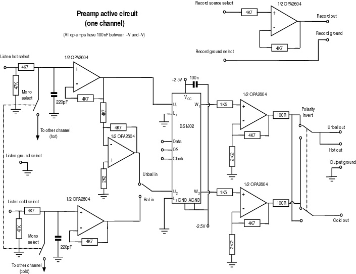
Most audio amplifier systems must have preamplifiers with many different characteristics. These include high-gain linear response for magnetic microphones, low-gain linear response for tuners, and high-gain RIAA equalization for magnetic phone cartridges. To meet this broad requirement, most amplifier...
This document serves as a compilation of design notes, providing practical details as construction progresses, along with some photographs that will be included in due course. Currently, it functions as a progress report, blending immediate plans with actual construction,...
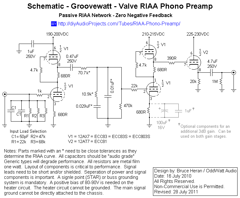
This project has been in development for over a year, initially postponed due to concerns about design complexity and the availability of high-quality phono preamps. The objective was to create a preamp that would deliver performance comparable to commercial...
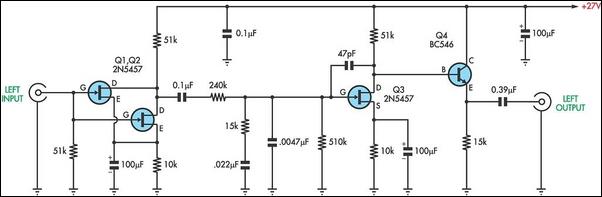
This is a specialized low-voltage version of an audio preamplifier. The emitter voltage of transistor T1 is biased close to half the supply voltage (1.5V) to enable maximum output voltage swing. Both transistors are directly coupled and utilize closed-loop...
There are two types of preamplifiers for magnetic phono cartridges. The most common type includes an RIAA equalization network in the feedback loop, as described in the March 2002 issue of SILICON CHIP. The second type, previously used in...
There are many individuals interested in listening to frequencies within the VHF range of 108 to 132 MHz. This VHF AM converter is designed to convert signals from a frequency band of 106 to 150 MHz, allowing users to...