
Rf driver audio oscillator circuit diagram

The audio oscillator circuit utilizes the 555 timer in astable mode, which enables continuous oscillation and generation of a square wave output. The configuration consists of a 555 timer IC, two resistors (R1 and RP1), and a capacitor (C1). The timing components, R1 and RP1, along with C1, determine the frequency of oscillation, allowing for a wide range of audio frequencies suitable for various applications.
In this circuit, R1 is a fixed resistor, while RP1 is a variable resistor (potentiometer), which provides the flexibility to adjust the oscillation frequency. The capacitor C1 acts as the timing capacitor, and its value, in conjunction with the resistors, directly influences the charge and discharge times, thus affecting the frequency output.
The formula f = 1.44 / ((R1 + 2 * RP1) * C1) indicates that the frequency is inversely proportional to the total resistance and capacitance in the circuit. By increasing the resistance of RP1, the frequency decreases, allowing for lower audio tones, while decreasing the resistance raises the frequency, producing higher tones. This range of 600 Hz to 20 kHz encompasses the audible spectrum, making the circuit suitable for applications such as tone generation, sound synthesis, and audio signal modulation.
The output from the 555 timer can be used to drive speakers or other audio devices, and additional filtering or amplification stages can be included in the design to enhance audio quality or drive larger loads. Proper selection of components is crucial to ensure stability and performance across the desired frequency range.As shown in the figure, 555, Rl, RPland C1form thecontrolled audio oscillator, f = 1.44 / ( R1 +2 RP1) C1, the icon parameter frequency isbetween 600Hz ~ 20kHz, and it can beselected by adjusting RP1.. 🔗 External reference
Related Circuits
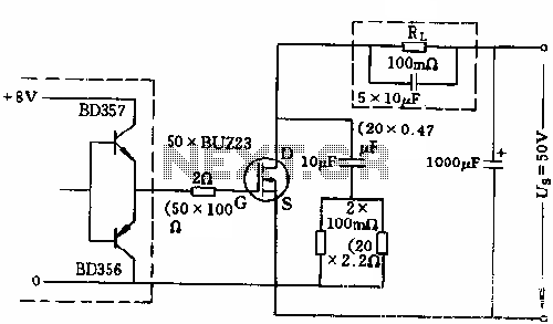
The circuit employs 50 BUZ23 field effect transistors (FETs) arranged in parallel, with a tube blocking voltage of 100V. The control power required is minimal, eliminating the risks associated with second breakdown and the positive temperature coefficient phenomenon in...
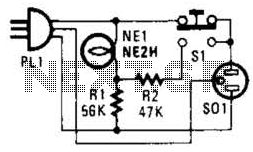
If residing in a cold climate, it is reassuring to confirm the functionality of an engine-block heater. This device indicates whether the heater is operational. To use, connect PL1 to a power outlet; the NE1 indicator should illuminate. Next,...
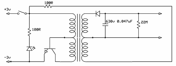
Free energy motors and generators are available for purchase, featuring plans for overunity devices. These devices resemble oscillators used in Joule thief circuits, although there may be some errors present in the designs. However, the concept remains clear. Free energy...
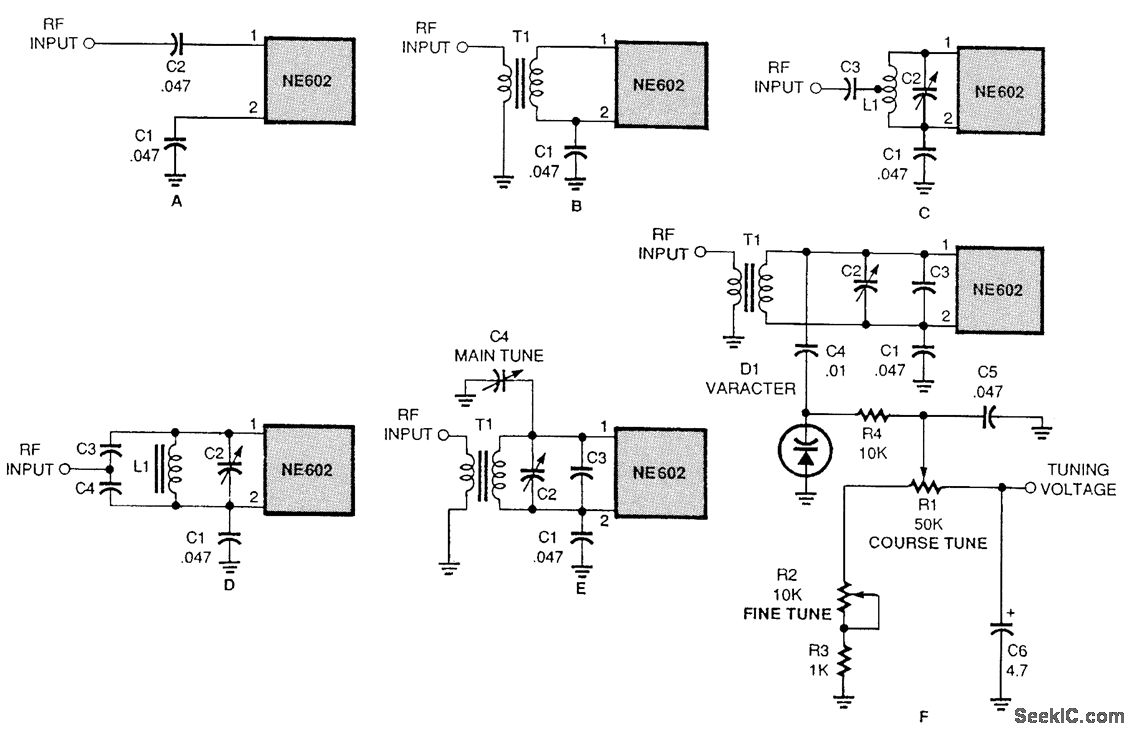
There are several methods to input a signal into the NE602. Simple untuned approaches (a and b) are viable. For tuning to a specific frequency, an LC resonant circuit with ungrounded trimmer capacitors (c and d) or grounded variable...
%2Busing%2Bop%2Bamp%2B741%2Bic%2B.png)
A zero crossing detector (ZCD) is a voltage comparator that switches its output between +Vsat and -Vsat (where Vsat is the saturation voltage, approximately 14V) when the input crosses the zero reference voltage. Comparators are fundamental operational amplifier circuits...
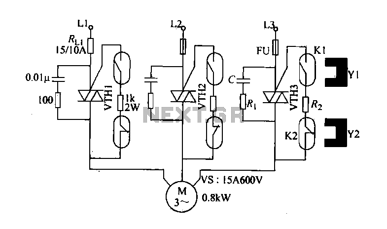
The circuit diagram illustrates a female textile machine power control circuit. VTH1-VTH3 represent TRIACs, while R and C form the absorption line. Rz serves as the triggering current limiting resistor. K1 is designated for starting the reed, and K2...