
A water tank automatic control circuit

The circuit utilizes a NE555 timer IC configured in a monostable mode to control the operation of a pumping system based on water level detection. The initial voltage reduction from 3.40V to 6.3V is crucial for the proper functioning of the NE555, as it operates effectively within this voltage range. The C1 capacitor acts as a filter, smoothing out any voltage fluctuations that may occur during operation, ensuring stable performance of the caution circuit.
In this setup, the water level is monitored by a sensor connected to points A and B. When the water level rises to point A, the voltage across resistor R increases, which is sensed by pin 6 of the NE555 timer. Once this voltage reaches 2/3 of the supply voltage (VDD), the output at pin 3 transitions to a low state. This action deactivates the relays K1-1 and K1-2, thus stopping the motor and preventing overflow.
The dual relay configuration allows for redundancy and safety in the pumping operation. The K1-1 relay is responsible for starting the pump, while K1-2 serves as a safety mechanism to ensure the pump does not operate under certain conditions. The shorting of wiring at point C ensures that the system can quickly respond to changes in water levels, maintaining efficient operation.
The toggle button K2 provides manual control over the water gate, allowing for intervention when necessary, such as during maintenance or exploration. The design emphasizes reliability and responsiveness, making it suitable for various applications where water level management is critical.After 3t40V power Sutra T seats is reduced to 6.3V low voltage by VDi - V sulfone full transition rectified. c1 filter provide after - when caution circuit NI/555 operating vol tage: NE555 (2) llt when canthus under military drawdown point B; 0 showed a low position, Chong Mi touch internal circuit overturns, Rotary (3) pin output high power semi-relay action was electric, dual touch n - K1 -l closed Yu pumping motor is activated while closing Kl 2 B. Point C are shorted wiring: When the water level rose to the point A t i inch, the power supply voltage over R.
Tan. Office points to NE555 (2), (6) feet away from the potential promoted to potential. (6) feet too trigger-based circuit provider side, when the voltage reaches 2/3VDD lq born of the circuit that is pulled over so (3) pin output goes low, J first electric release Kl - I, Kl -2, the motor stops JL work. BG connection contacts jump AB heap line is short-circuited. fb-like nervous waiting to enter the road. Live below the water level is higher than the Dong A point B point. Toggle buttons K2 Oh boom in exploration will draw water gate.
Related Circuits
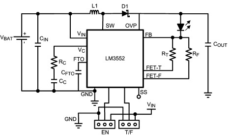
For this LED driver electronic project, a DC power supply circuit is required to provide an output voltage between 2.7V and 5.5V. The supply voltage must be applied between Vin and GND. The T/F jumper connects the T post...
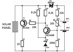
The nominal voltage of the solar charger circuit module is determined by the number of battery cells to be charged. Due to the typical voltage drop of 0.3 to 0.4 V across Schottky diode D1, the nominal voltage should...
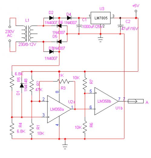
Create a temperature-controlled fan circuit using a 15V AC power supply instead of a 230V AC supply. Clarification is needed on whether it is necessary to change the triac and resistor in the provided diagram. Additionally, it is important...
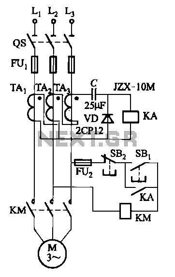
Figure 4-27 (b) line demonstrates a configuration that enhances the output current waveform DC voltage compared to the line in Figure 4-27 (a). This configuration can be utilized for motors with larger capacities. The circuit illustrated in Figure 4-27 (b)...
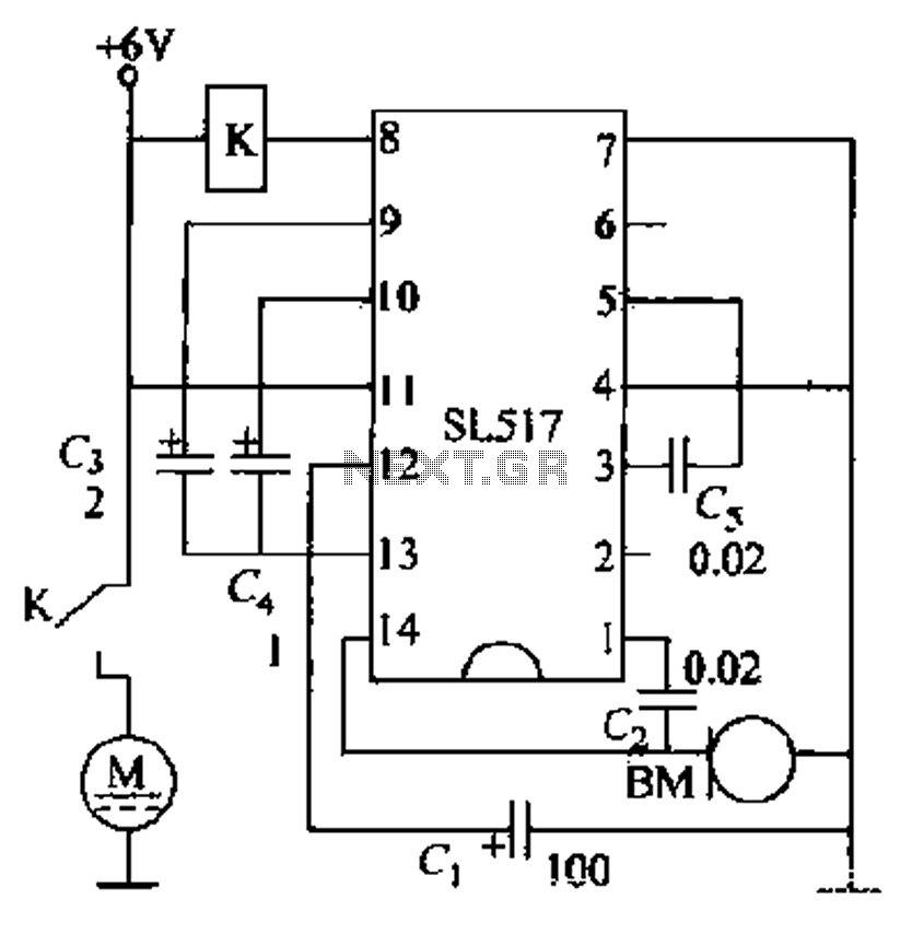
Electric cars utilize a voice circuit principle, where sound signals are captured by a microphone (BM) and processed. The signal is then coupled through a capacitor to an integrated circuit (IC), which includes an internal amplifier that boosts the...
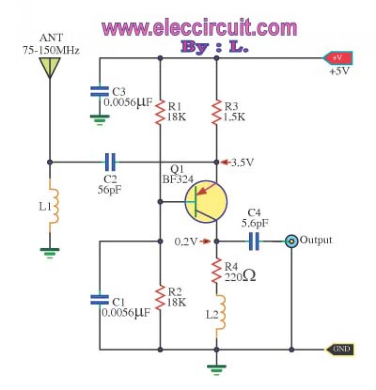
This is a wideband high-frequency amplifier circuit designed for a frequency range between 75-150 MHz. It utilizes a PNP transistor amplifier to enhance signal strength before it reaches the receiver of devices such as phones, FM radios, or amateur...