
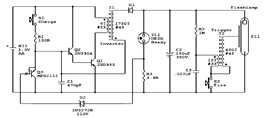
MC81 holiday lights ASIC

A 220V AC power supply is integrated into the circuit, utilizing a VDI ~ VD4 bridge rectifier to convert the AC voltage into a usable DC format. This rectified voltage powers two indicator lights, Hl and H2, which serve as visual signals within the system. The inclusion of resistors Rl and R2 is critical, as they limit the current flowing to the capacitors C1 and C2. These capacitors function as filters in the power supply, smoothing out voltage fluctuations and ensuring stable operation.
The internal MC81 regulators are a notable feature, as they allow the circuit to function effectively without necessitating an external voltage regulator. However, for optimal performance, it is recommended to include a current-limiting resistor to prevent excessive current from damaging the components.
The circuit design incorporates a manifold that drives SCRs (Silicon Controlled Rectifiers) VSI and VZ, which are responsible for controlling the flashing of the indicator lights. This setup allows for dynamic light patterns that can enhance the visual appeal of the circuit.
For audio output, a 5-pin connection is utilized to amplify the music signal through an external transistor (VT). This transistor drives a piezoelectric ceramic speaker (B), which produces sound. The circuit is configured to enhance the sound volume of the piezoelectric ceramics by utilizing resistor R1 as a voltage supply, ensuring that the sound output meets the desired specifications.
The user interface includes a button switch (SB) that does not lock, allowing users to change the light and music settings with each press. This feature provides flexibility in adjusting the volume levels between large, medium, and small settings, enhancing the user experience by allowing for immediate changes without the need for specific selection mechanisms. Overall, this circuit effectively combines visual and auditory elements, making it suitable for various applications requiring synchronized light and sound output.220V AC by VDI ~ VD4 bridge rectifier, lights the way for Hl, H2 electricity, another pass Rl, R2 two resistors buck, limiting the capacitor CI, C2 filter manifold A power supp ly (due to internal MC81 Regulators have been, so the external circuit without providing the regulator, but the need to add a current limiting resistor buck). Manifold l, 2 feet directly drive SCR VSI, vsz to control lights flashing string Hl and H2. 5-pin output music signal amplification through external transistor VT to drive the piezoelectric ceramic hair B sound.
To increase the sound volume of piezoelectric ceramics, the power transistor using only R1 a resistance voltage supply. SB no lock button switch, each press to change the light-hop music with the size, can sound large, medium and small between no choice.
Related Circuits
The circuit diagram illustrates the original Kodak MAX Flash Unit, including the semiconductors that comprise the circuit. This diagram represents the unmodified version intended for the standard Kodak model, which should closely resemble the Kodak MAX model, if not...
A 2003 Monte Carlo SS is experiencing issues with low idling, causing the engine to stall while driving or when parked. Additionally, the dashboard lights are malfunctioning; they occasionally activate for a brief moment before turning off again. There...
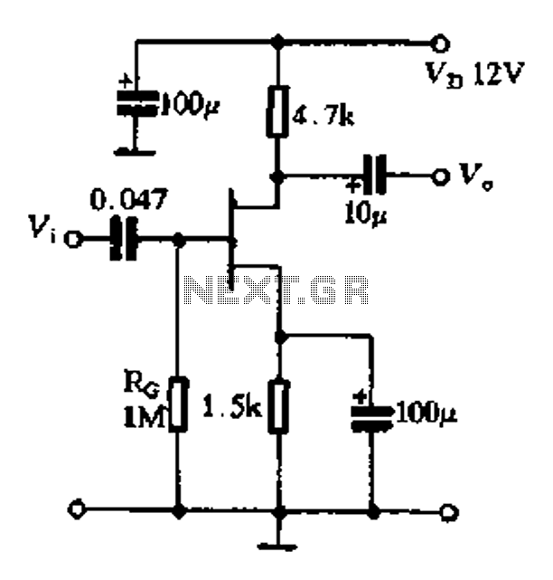
The FET exhibits a high input impedance, a low noise figure, anti-crosstalk capabilities, and good mutual interference performance, making it increasingly utilized in electronic circuits. FET amplifiers can be configured in various ways, including as common source (equivalent to...
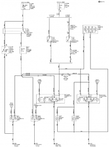
The connection and wiring between each part and component of the exterior lighting system of the vehicle includes elements such as the fusible link, junction block, tail light relay, cruise control, stop light switch, relay box, column switch, rear...
The 2003 GMC Savana has issues with the illumination lights for the instrument cluster and climate control cluster, which are not functioning. Diagnostic lights for the cluster are operational and illuminate upon ignition startup. The radio lights are functioning...
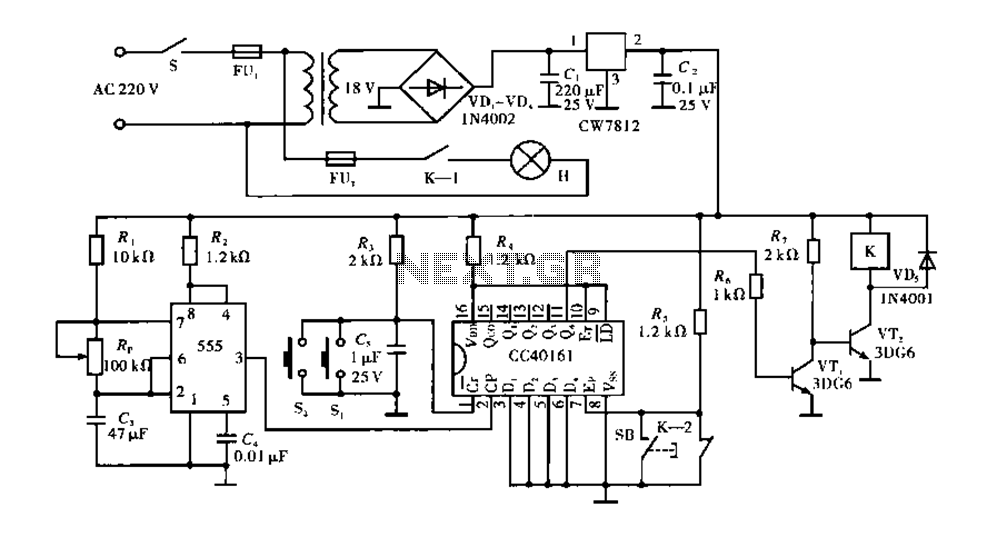
Corridor counter delay circuit for controlling lights. This circuit is tested and functional. When the circuit is energized, the 555 oscillator starts to oscillate. The CC40161 is cleared, and an integrating circuit composed of R3 and C5 transitions the...