
Musical Doorbell Circuit

The musical doorbell circuit utilizes a combination of digital and analog components to create an interactive sound output based on user input. The core of the circuit is the 4015 static 4-bit shift register, which holds binary data that represents different melodies. The user interaction begins with the pressing of switch S1, which serves as the input trigger for the system. This switch closure alters the logic levels at the inputs of U3 and U1, initiating the melody playback sequence.
The clock generation is handled by U4, which provides a consistent timing pulse at approximately 5 Hz. This frequency determines how quickly the shift register advances its stored data. The duration for which the switch S1 is pressed directly influences the number of shifts that occur within the register, hence affecting the length of the melody played.
As the logic 1 is shifted through the register, it activates the base of transistor T1, which functions as a current-controlled oscillator. The oscillation frequency, and thereby the pitch of the tones produced, varies based on the specific outputs of the shift register that are active at any given moment. The feedback loop from pin 2 of the shift register back to U2 and U3 ensures that the circuit continuously cycles through the stored melodies, providing a dynamic and engaging auditory experience.
This design effectively combines digital logic with analog control to create a versatile musical doorbell that responds to user interaction in a meaningful way. The result is a circuit that not only serves its primary function as a doorbell but also adds an element of playful interaction through its musical capabilities.This featured circuit is a musical doorbell. After the button S1 is pressed, a short melody is played. When the button is pressed many times in rapid succession or pressed longer, a different melody is generated and the melody plays longer. The circuit works this way: when the button S1 is activated the inputs of U3 and one input of U1 switches to logic 0 ³.
The data input (pin 7 of IC 4015) becomes logic 1 ³. The 4015 is a static 4-bit shift register. Each clock impulse coming from U4 shifts this logic 1 ³ further in the register. The clock frequency is around 5 Hz. The number of shifted logic 1 ³ is directly dependent on the length of time the switch S1 is closed. Once at least one shift register is logic 1 ³, a current flows to the base of T1 through a corresponding resistor. The transistor T1 functions as a current controlled oscillator. The tone pitch is dependent on the logic state of the different flip-flop outputs of the shift register.
Each clock pulse shifts the logic 1 ³ in the register. One output of the register (pin 2) is coupled back to U2 and U3 so that all the logic 1 ³ in the register always run in a loop. 🔗 External reference
Related Circuits
The integrated circuit LM386 is a low-power audio frequency amplifier that requires a low-level power supply, typically batteries. It is available in an 8-pin mini-DIP package. The IC is designed to provide a voltage amplification of 20 without the...
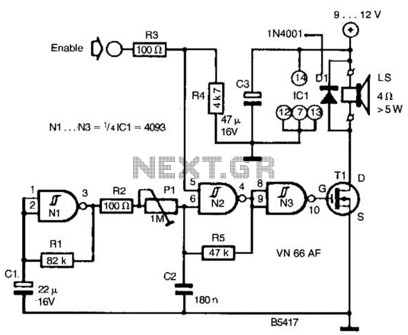
A CD4093 chip and several components form a siren oscillator that drives power MOSFET Tl. A speaker is directly powered by this device. The siren is activated by a logic high signal applied to the ENABLE input. The circuit comprises...
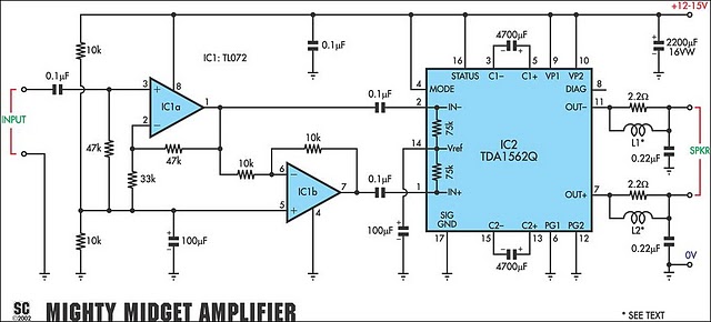
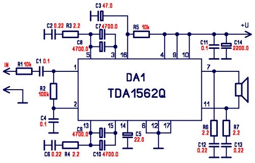
It is based on a Philips class-H audio amplifier IC and can deliver 36W RMS or 70W music power, all from a 13.8V supply. The Mighty Midget Amplifier can provide approximately 36W RMS continuous power into a 4-ohm load...

The input capacitor is used for low-frequency cut-off, with a standard value of 0.1 µF, resulting in a cut-off frequency of approximately 16 Hz. The input capacitor plays a critical role in electronic circuits, particularly in signal processing and audio...
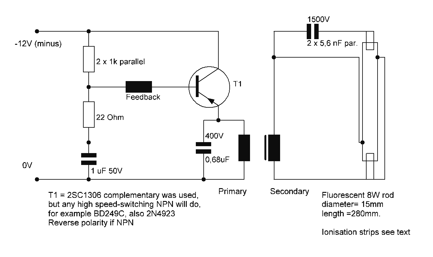
Starting a fluorescent lamp on an inverter can be challenging due to the trade-offs involved in achieving optimal operating efficiency with 12V drivers. Fluorescent lamps require a specific starting voltage to ionize the gas within the tube and initiate the...
The LM3886 amplifier electronic circuit project is designed to deliver 68W of continuous average power into a 4-ohm load and 38W into an 8-ohm load with a total harmonic distortion plus noise (THD+N) of 0.1% across the frequency range...