
Medical ultrasonic atomizer 2

The medical ultrasonic atomizer circuit is designed to efficiently generate mist from a liquid, which is particularly useful in medical applications such as respiratory therapy. The power supply circuit plays a crucial role in providing the necessary voltage and current to the entire system. The timer (Q) is responsible for controlling the operation time of the atomizer, ensuring that the device operates only when required. Fuses (FU1, FU2) are included for overcurrent protection, safeguarding the circuit from potential damage due to excessive current flow.
The power transformer (T) steps down the mains voltage to a suitable level for the circuit. The bridge rectifiers (UR) convert the alternating current (AC) output from the transformer into direct current (DC), which is then smoothed by the filter capacitor (C1) to provide a stable voltage supply. Resistors (R1, R2) are used to limit current and set biasing levels for various components, while the LED (VL) serves as a power indicator, illuminating when the circuit is active.
The atomization amount and liquid level detection control circuit is integral for ensuring optimal operation of the atomizer. Resistor (R3) and potentiometers (RP1, RP2) are utilized for adjusting the sensitivity and response of the liquid level detection system. The magnetic control water level switch (SA) operates based on the position of a float, which rises and falls with the liquid level. The embedded magnetic ring activates the reed switch when the liquid reaches a certain level, providing feedback to the control circuit. Capacitor (C2) is used for stabilizing the control signal and filtering out noise, ensuring reliable operation of the liquid level detection system.
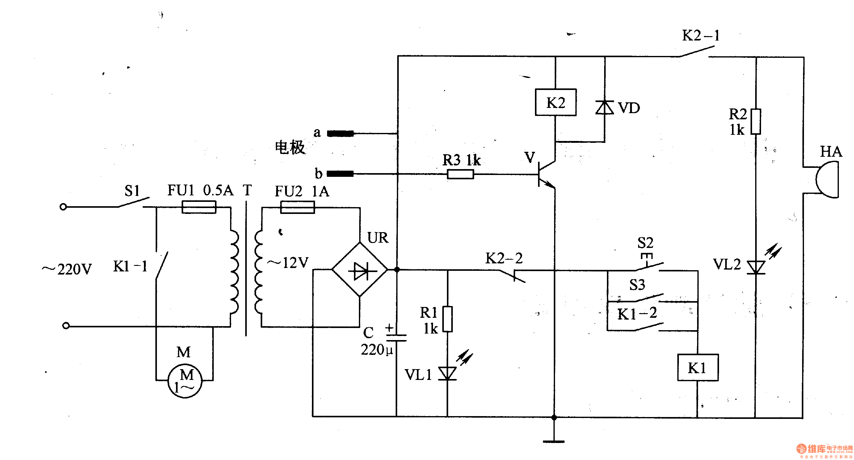
Overall, this circuit design provides a comprehensive solution for atomizing liquids in a controlled manner, utilizing ultrasonic technology for effective mist generation while incorporating safety features and responsive control mechanisms.The medical ultrasonic atomizer circuit is composed of power supply circuit, atomization amount liquid level detection control circuit, ultrasonic oscillator and fan motor M, it is shown in the figure 9-111. The power supply circuit is made of timer Q, fuses FU1, FU2, power transformer T, bridge rectifiers UR, resistors R1, R2, LED VL and filter c
apacitor C1. The atomization amount/liquid level detection control circuit consists of resistor R3, potentiometers RP1, RP2, magnetic control water level switch SA(it is composed of float with magnetic ring and reed switch)and capacitor C2. 🔗 External reference
Related Circuits
The working principle of the circuit pertains to a medical electric aspirator waterproof controller, which includes a power supply circuit, a liquid level detection control circuit, and an alarm circuit, as illustrated in Figure 9-47. The power supply circuit...
The performance of this sensitive ultrasonic receiver is impressive. It allows users to listen to various sources of ultrasonic sounds, including bugs, bats, and engines. The circuit utilizes a piezo tweeter as an ultrasonic microphone, with amplifier stages Q1...
I have found this circuit to have better sensitivity, both in distance to a visible bat and in audio frequency, than some other published circuits using a 40kHz transducer with 4000x gain amplification, though the 40kHz transducer I used...
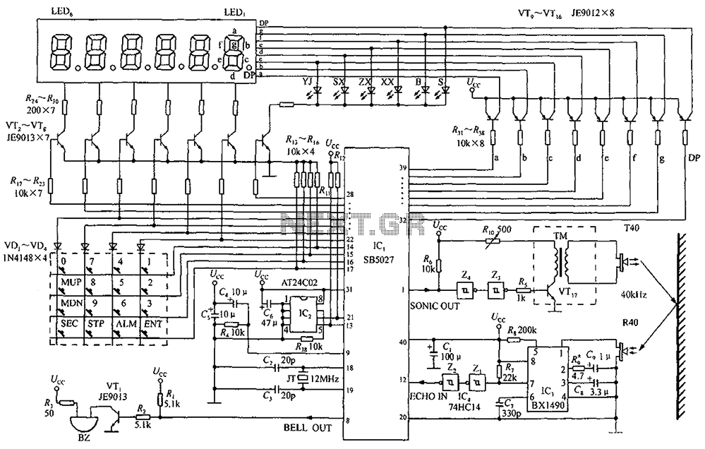
A circuit diagram of an ultrasonic range finder is constructed using a clock with a calendar and the Ultrasonic Ranging IC SB5027. The ultrasonic range finder circuit utilizes the Ultrasonic Ranging IC SB5027, which is designed to measure distances by...
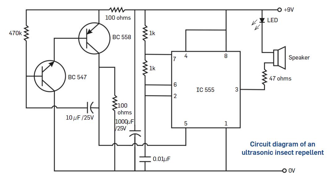
Many types of insects are sensitive to ultrasonic sounds, which can cause them irritation. This project is designed to repel insects such as mosquitoes and cockroaches using ultrasonic sound waves. The project utilizes an ultrasonic frequency generator, which emits sound...
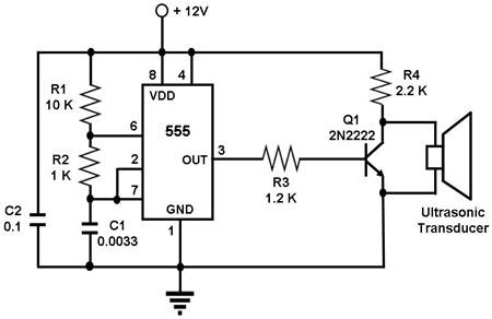
The circuit utilizes a 555 timer integrated circuit (IC) configured as an astable multivibrator, which generates a continuous signal at a specific frequency as long as its reset pin (pin 4) is held high. The ultrasonic transducer employed in...