
The medical electric aspirator waterproof controller (2)
")
The medical electric aspirator waterproof controller operates through an integrated design that ensures reliable performance in clinical environments. The power supply circuit serves as the foundation of the system, converting the input voltage to a usable level for the other components. The switch S1 allows for the manual activation and deactivation of the system, ensuring that the device can be turned off when not in use to conserve energy and enhance safety.
Fuses FU1 and FU2 are critical for protecting the circuit from overcurrent conditions, which can lead to component damage or failure. The power supply transformer T steps down the voltage to the appropriate level required by the circuit, while the power supply indication LED VL1 provides visual feedback to the user, indicating that the device is powered and operational.
The liquid level detection control circuit is designed to monitor the fluid levels within the aspirator. This circuit typically employs sensors that detect the presence or absence of liquid, triggering alarms if levels fall outside of predetermined thresholds. This feature is essential for preventing overflow and ensuring the safe operation of the aspirator.
The alarm circuit is an integral part of the system, alerting users to any irregularities in operation, such as low fluid levels or circuit malfunctions. This circuit enhances user safety and ensures that the aspirator functions correctly, providing timely notifications for maintenance or intervention.
Overall, the comprehensive integration of these components within the medical electric aspirator waterproof controller ensures effective operation, safety, and reliability in medical applications.Working principle of the circuitThis medical electric aspirator waterproof controller consists of the power supply circuit, liquid level detection control circuit and alarm circuit, see as figure 9-47. The power supply circuit consists of the switch S1, fusees FU1 and FU2, power supply transformer T, power supply indication LED VL1, rectifier bridge file UR..
🔗 External reference
Related Circuits
The figure illustrates a preset outage timer circuit designed for an electric cooker. The timing range of the circuit extends from 1 hour to 12 hours, adjustable via a potentiometer (PR). The timing mode operates on a counting basis,...

This is a simple basic design of a servo motor controller with a pulse generator. It utilizes the CMOS IC 7555 in astable mode to generate pulses for driving the motor. The servo motor controller circuit employs the CMOS IC...
This project automates home appliances via a Bluetooth-enabled PC. A USB Bluetooth adapter is utilized on the PC side, while a Serial Bluetooth module is employed for communication. This project involves the integration of a Bluetooth-enabled PC with home appliances...
A dimmer switch is an electrical device that can replace standard switches used for lamps, heaters, or certain types of electric motors. Dimmer switches allow for the adjustment of light intensity and power levels. Dimmer switches operate by varying the...

High brightness (HB) and super HB LEDs are utilized in LCD TFT backlighting for high-end televisions, industrial lighting, and projectors. A notable application is in instrument panel backlighting, interior lighting, and brake lights of various vehicles. Luxury automobile manufacturers...
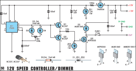
This circuit serves as a speed controller for a 12V motor rated up to 5A (continuous) or as a dimmer for a 12V halogen or standard incandescent lamp rated up to 50W. It modulates the power to the load...