
Metal detector 7

The metal detector circuit functions based on the principles of oscillation and resonance within an LC circuit. The oscillating tube (V) generates a high-frequency signal, which is modulated by the presence of metal objects in proximity to the detection coil (L). The detection coil is a critical component, as it is responsible for sensing changes in the electromagnetic field caused by metallic objects.
The resonant capacitor (C1) works in conjunction with the inductance of the coil (L) to establish a resonant frequency, which is tuned to the desired operating frequency of the circuit. The variable resistor (R) allows for fine-tuning of the circuit's sensitivity, enabling the user to adjust the detection threshold based on environmental conditions.
The choice of capacitors (C2 and C3) is essential for maintaining the stability and performance of the circuit at high frequencies. High-frequency ceramic or glaze capacitors are preferred due to their low equivalent series resistance (ESR) and excellent frequency response characteristics.
The PNP germanium transistor (V) serves as an amplifier, boosting the signal generated by the oscillating tube to drive the speaker. The 9V laminated battery (GB) provides the necessary power supply for the entire circuit, ensuring reliable operation.
The construction of the coil (L) is also vital for the performance of the metal detector. The specific dimensions and number of turns are designed to optimize the inductance and sensitivity of the coil. By increasing the diameter of the coil to 30 cm, the detection range can be enhanced, allowing for the detection of larger or deeper metal objects. The recommendation to keep the coil parallel to the ground is crucial for achieving optimal performance and sensitivity during operation.
Overall, this metal detector circuit offers a practical application of basic electronic principles, combining oscillation, resonance, and amplification to detect metallic objects buried underground.That metal detector circuit uses LC single-tube oscillator circuit, it is shown as Figure 8-73. In the circuit, V is oscillating tube, L is the detection coil, Cl is the resonant capacitor. After turning on power switch S, the LC single-tube oscillator circuit starts oscillation, semiconductor superheterodyne radio speaker will issue the sounds with the frequency in lkHz. When the search coil L detects underground metal, the radio frequency of the sound of the speaker becomes high. Component`s selection R uses variable resistor (270P seal simply connected); C2 and C3 use high frequency ceramic capacitor or glaze capacitors.
V selects 3AGl or 3AGIl High Frequency Low Power PNP germanium transistors. GB uses 9V laminated battery. L uses enameled wire with †O · 5lmm which is winded on the 5mmxlOmmx8Omm magnet bar with 80 turns (60 turns at the tap, W1 has 60 turns, W2 has 20 turns. ) For increasing the sensitivity of L, it can also be winded the coil with the diameter in 3Ocm, the coil should be parallel to the ground.
🔗 External reference
Related Circuits
The search loop can be constructed in various ways; however, the method presented here should provide a solid foundation. Refer to Fig. 2 as a guide for assembling the loop. The loop should be made from non-metallic and moisture-resistant...
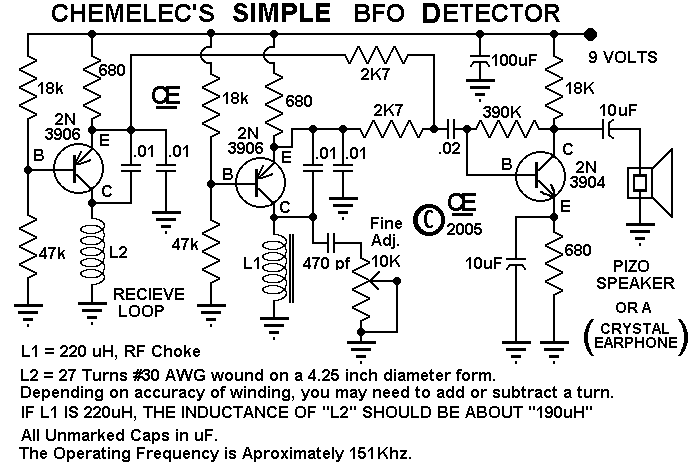
A Very Simple "Beat Frequency Oscillator" type of Metal Detector. These are about the Simplest of all Metal Detector types, But still quite useful for many Detecting applications. And although this one is particularly simple, it works very well. The...
One LED monitors three levels: 50, 70 & 85 dB. Useful to detect too noisy environments. This circuit is intended to signal, through a flashing LED, the exceeding of a fixed threshold in room noise, chosen from three fixed...
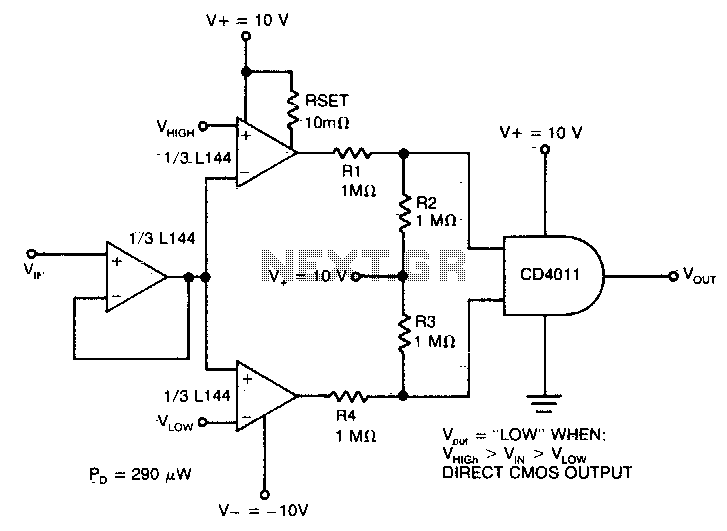
The detector utilizes three sections of an L144 and a DC4011 type CMOS NAND gate to create a very low power voltage monitor. If the input voltage, Vin, is above Vhigh or below Vlow, the output will be a...
The core of this overheat detector circuit features a precision integrated temperature sensor, the LM35 (IC1). This sensor provides a linear and directly proportional output in millivolts over a temperature range of 0 to +155 degrees Celsius. The LM35...
This homemade metal detector circuit is designed to locate objects made of materials with relatively high magnetic permeability. While it may not be sensitive enough for detecting buried coins, it can effectively identify larger metallic treasures. The circuit operates...