
Whistle Responder Schematic circuit

The circuit design employs an electret microphone that converts sound waves into an electrical signal. The output from the microphone is fed into the first inverter (IC1A), which amplifies the signal to a usable level. The amplified signal is then routed to the second inverter (IC1B), where it passes through a band-pass filter. This filter is crucial as it allows only the desired frequency range (approximately 1.8 kHz) to pass while attenuating other frequencies, thereby reducing false triggering caused by background noise.
The output from the band-pass filter is then processed by the Schmitt trigger (IC1C). The Schmitt trigger is designed to provide a clean digital signal by converting the analog audio signal into a square wave, which is more suitable for digital processing. This square wave is then fed into a monostable multivibrator (IC1D), which generates a pulse of a fixed duration (two seconds) in response to the detected whistle.
Following the monostable multivibrator, the circuit transitions to an astable multivibrator configuration formed by IC1E and IC1F. This configuration generates a continuous square wave output at a frequency between 3 to 5 Hz, which is used to drive the transistor (Q1). The transistor acts as a switch, controlling the current flow to the buzzer (BZ1). When the transistor is activated, the buzzer produces an intermittent sound, effectively alerting the user to the detected whistle.
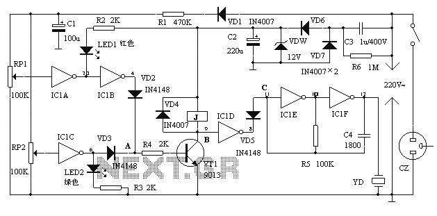
In summary, this circuit effectively combines audio amplification, frequency filtering, signal conditioning, and timing functions to create a responsive and reliable whistle detection system that provides audible feedback through an intermittent beeping sound.This device beeps intermittently for about two seconds when a person in a range of around meters emits a whistle. The first two inverters contained in IC1 are used as audio amplifiers. IC1A amplifies consistently the signal picked-up by the small electret-microphone and IC1B acts as a band-pass filter, its frequency being centered at about 1.8KHz.
The filter is required in order to select a specific frequency, the whistle`s one, stopping other frequencies that would cause undesired beeper operation. IC1C is wired as a Schmitt trigger, squaring the incoming audio signal. IC1D is a 2 second-delay monostable driving the astable formed by IC1E & IC1F. This oscillator generates a 3 to 5Hz square wave feeding Q1 and BZ1, thus providing intermittent beeper operation..
🔗 External reference
Related Circuits
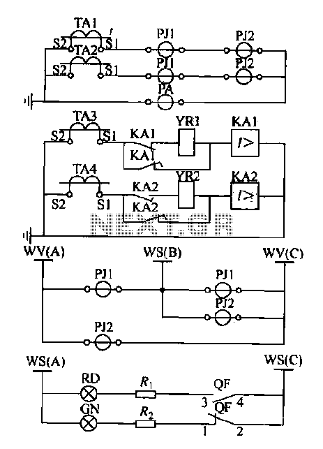
Expanding schematic circuit for the secondary circuit of high-voltage lines. The schematic circuit for the secondary circuit of high-voltage lines is designed to enhance the distribution and management of electrical power in high-voltage systems. This circuit typically includes components...
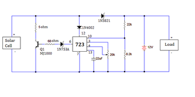
The ultimate source of energy is the Sun. It is possible to generate current from sunlight using solar panels. These panels convert light energy into electrical energy. A solar panel consists of a number of solar cells, which produce...
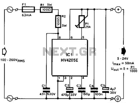
Direct derivation of 5 to 24 Vdc from AC mains without a transformer is possible with this circuit. Note that a direct mains connection to the DC output exists. Suitable safety precautions must be taken. This circuit design allows for...
The alarm protection can trigger a sound and light alert when the mains voltage exceeds or falls below a predetermined threshold. It automatically disconnects the electrical power supply without damaging the electrical protection. The device is compact, fully featured,...
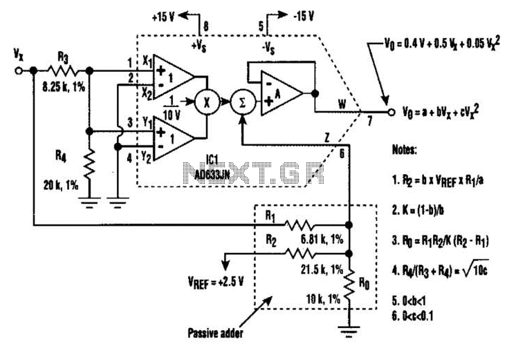
A circuit utilizing a single analog multiplier and five precision resistors can produce an output voltage (Ko) that represents a second-order polynomial. This circuit implements the quadratic function. The input terminals of IC1 are configured to create a positive...
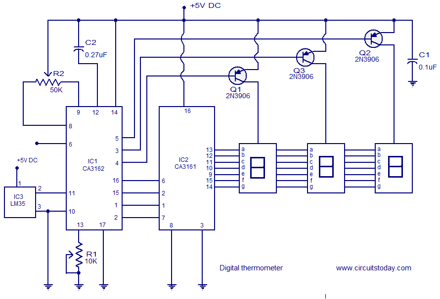
A simple digital thermometer circuit without a microcontroller and featuring a seven-segment LED readout is presented. The circuit utilizes three integrated circuits (ICs): CA3162, CA3161, and LM35. The CA3162 is a monolithic analog-to-digital (A/D) converter with a BCD output....