
Metal detector circuit diagram 3

The metal detector circuit is designed to detect metallic objects by utilizing a combination of oscillators and amplification stages. The probe oscillator generates a varying electromagnetic field through the detection coil L1, which interacts with nearby metallic objects. The resulting changes in the oscillation frequency are detected and processed by the reference oscillator. The reference oscillator, comprising transistors V1 and V3 along with inductor L2 and capacitor C3, stabilizes the frequency and provides a reference signal against which the probe oscillator's output can be compared.
The audio amplifier section, which includes an audio power amplifier IC, serves to amplify the audio signal generated by the detection process. The volume potentiometer RP allows for adjustment of the output audio level, ensuring that the user can hear the detected signals clearly. Capacitors C6 to C8 are employed to filter and stabilize the audio signal, enhancing the overall performance of the amplifier.
Resistors R1, R2 to R5 are carefully selected to ensure the proper functioning of the circuit. R1, being a small or variable resistor, may be used for fine-tuning the sensitivity of the probe oscillator. The 1/4W metal film resistors R2 to R5 provide stability and accuracy in the circuit's operation. The choice of capacitors, including high-frequency ceramic and aluminum electrolytic types, is critical for maintaining signal integrity and ensuring reliable performance across various operating conditions.
Overall, the metal detector circuit exemplifies a well-integrated design that balances sensitivity, stability, and user control, making it an effective tool for detecting metallic objects in various environments.The metal detector is composed of the probe oscillator, reference oscillator and audio amplifier and other components, and the circuit is shown as the chart. Probe oscillator consists of transistors VI, V2 and detection coil L1, capacitor C1 and so on. Reference oscillator consists of transistors VI, Y3 and inductor L2, capacitor C3 and other comp onents. Audio amplifier is composed of audio power amplifier IC IC, volume potentiometer RP and capacitors C6 ~ C8 RP and so on. R1 uses small or variable resistor; R2 ~ R5 select 1/4W metal film resistors. RP uses small membrane potentiometer. C1 uses high-frequency ceramic capacitor; C2, C5 ~ C8, CIO use aluminum electrolytic capacitor with the voltage in 10Y; C3 uses ceramic fine capacitor; C4, C9 select polyester or monolithic capacitors.
🔗 External reference
Related Circuits
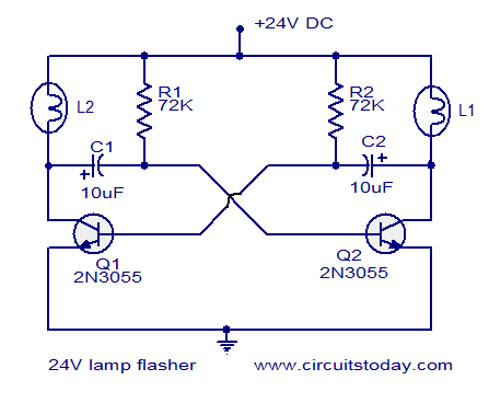
The circuit operates on 24V DC and is designed to alternately flash two 24V bulbs. It functions as an astable multivibrator with a frequency of 1Hz and a duty cycle of 50%. The lamps to be flashed are connected...
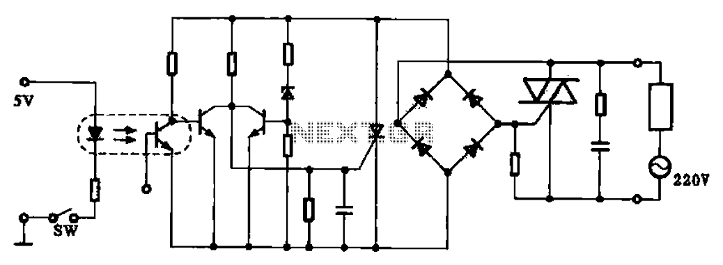
This application example illustrates a photovoltaic control circuit. In this circuit, the Triac functions as a solid-state relay, providing an AC power supply path to the load. It is designed to achieve high current control signals using a small...
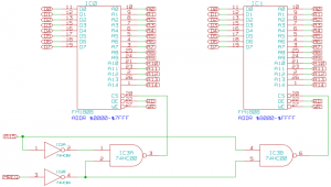
The memory component of the Mark 2 system is quite straightforward. It consists of two 32K SRAM chips, which are actually FRAM due to availability, but this does not impact functionality in this context. The selection of these chips...
This circuit primarily relies on a voltage regulator. The 7809 voltage regulator can provide a continuous output of up to 2 amps while ensuring a low noise and highly regulated supply. Although the circuit can function without additional components,...
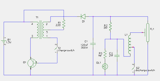
This document provides a step-by-step guide for modifying a disposable camera flash unit to serve as a power supply for a Geiger tube. The process involves removing the flash tube and trigger transformer from the circuit board by gently...
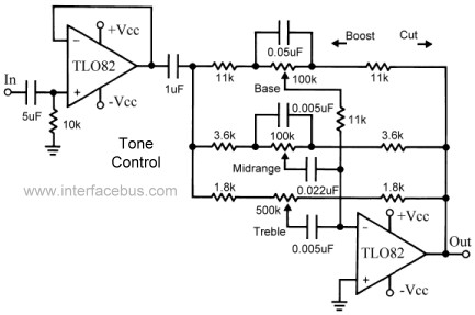
This topic continues the coverage of audio tone controls. The first entry started with a passive tone control circuit using different RC filter configurations and introduced an active filter. The second entry showed a fully designed 2-band active tone...