
Photoelectric high current small signal control circuit

The photovoltaic control circuit utilizes a Triac, which is a semiconductor device that can control power flow in AC circuits. When a small control signal is applied to the gate of the Triac, it allows a much larger current to flow through the load, effectively acting as a switch. This capability is particularly useful in applications where the control signal is generated from a low-power source, such as a photovoltaic cell.
In this configuration, the photovoltaic cell generates a small voltage when exposed to light, which is sufficient to trigger the Triac. Once triggered, the Triac remains conductive until the current through it drops below a certain threshold, allowing for efficient control of high-power devices with minimal input power.
The circuit typically includes additional components such as resistors, capacitors, and possibly optoisolators to ensure safe operation and to protect the control signal source from high voltages present in the AC circuit. The use of a Triac in this manner enhances the reliability and efficiency of the control system, making it suitable for a variety of applications including lighting control, motor speed control, and other automated systems where power management is essential.Application Example A photovoltaic control circuit, the figure of Triac is called solid state relays, load it provides AC power supply path. To achieve high current control sig nal with a small (low current).
Related Circuits
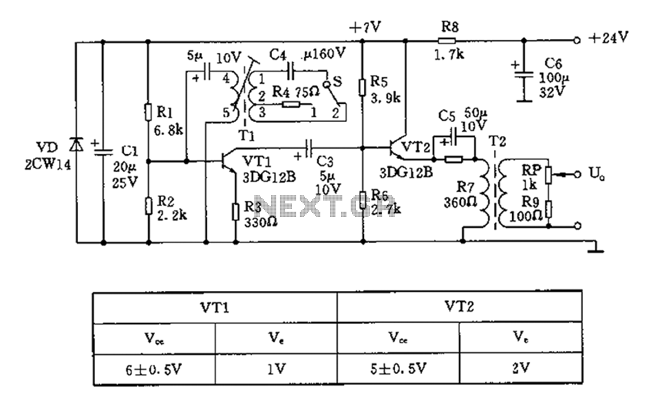
The 450/800Hz oscillation circuit depicted in the figure utilizes transformer coupling. The frequency conversion is achieved by varying the inductance through a variable filter tap (T1). When the switch control signal (S) is set to position 1, the oscillator...
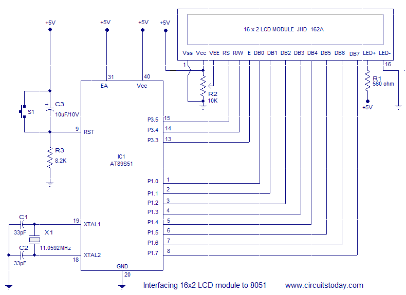
Interfacing a 16x2 alphanumeric LCD module with the AT89S51 microcontroller. The circuit diagram, theory, and program are included. JHD162 LCD module pinout and commands are provided. The integration of a 16x2 alphanumeric LCD module with the AT89S51 microcontroller involves several...

The 555 timer integrated circuit (IC) is an exceptionally versatile component utilized in various applications, including generating clock pulses, switch debouncing, and functioning as an output transducer. The standard 555 IC is packaged in an 8-pin configuration, available in...
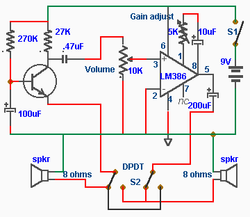
In this intercom schematic, an 8-ohm speaker is used as both a microphone and a listening speaker. A 10K potentiometer controls the volume, and the total gain can be adjusted. This intercom circuit utilizes an 8-ohm speaker in a dual...
AN12979A is a stereo BTL amplifier that includes an AGC circuit to prevent clipping at the speaker output. This integrated circuit (IC) can perform mode changes via the I2C bus control system, allowing for functions such as toggling the...
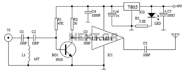
Circuit Overview Many families now own various electronic devices such as televisions, VCD players, video recorders, game consoles, cameras, and DVDs. This circuit involves an RF signal repeater designed to work with a television signal transmitter, covering a radius...