
Metal detector circuit diagram 8

The metal detector circuit operates by utilizing the probe oscillator to create a high-frequency signal that is modulated by the presence of metal objects in proximity to the detection coil. The detection coil (L) plays a crucial role in generating the oscillating signal, which is amplified by transistor (V1). Resistors (R1 to R3) and capacitors (C1 to C5) form the necessary components to stabilize and filter the oscillation frequency, ensuring optimal sensitivity and performance.
The PLL circuit, represented by integrated circuit (IC1), is designed to maintain a stable oscillation frequency by locking onto the frequency generated by the probe oscillator. Resistors (R4 to R8) and capacitors (C7 to C11) are used to configure the loop bandwidth and phase margin, which are essential for the system's response time and accuracy in detecting metal objects.
When metal is detected, the audio alarm circuit is activated. This circuit includes a comparison amplifier (IC2) that processes the output signal from the PLL circuit. If the signal exceeds a predefined threshold, transistor (V2) is triggered, allowing current to flow through the buzzer (HA), producing an audible alarm. Resistors (R9 to R14) are employed to set the gain and biasing conditions for the comparison amplifier, ensuring reliable operation under varying conditions.
The circuit is designed with specific power ratings for resistors to ensure reliability and prevent overheating. The use of 1/4W carbon film or metal film resistors for R1 to R14 provides a balance between cost and performance, while the 1/2W metal film resistor (R15) is selected for its ability to handle higher power dissipation. The variable resistor (RP) allows for fine-tuning of the circuit's sensitivity, providing flexibility for different detection scenarios.
Overall, this metal detector circuit effectively combines the functionalities of oscillation generation, frequency stabilization, and audio signaling to detect metallic objects, making it suitable for various applications in security, treasure hunting, and industrial environments.The metal detector circuit is composed of the probe oscillator, PLL phase-locked loop circuit and the audio alarm circuit, and the circuit is shown as the chart. Probe oscillator is composed of the detection coil L, transistor VI, resistors RI ~ R3, capacitors C1 ~ C5.
PLL phase-locked loop circuit consists of integrated circuit IC1, resistors R4 ~ R8, capacitors C7 ~ Cll. Audio alarm circuit is composed of the transistor V2, comparision amplifier integrated circuit IC2, buzzer HA, resistors R9 ~ R14. R1 ~ R14 use 1/4W carbon film resistors or metal film resistors; R15 uses 1/2W metal film resistor. RP uses small potentiometer or variable resistor. V1 and V2 use 59018 or 2SC1815 NPN silicon transistors. 🔗 External reference
Related Circuits
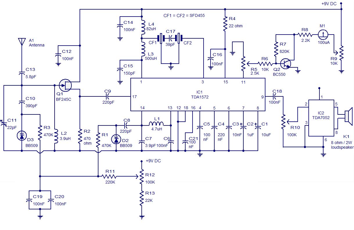
High-quality AM radio circuit based on the TDA1572 IC. The AM radio receiver circuit operates from 9V DC and has a 1W output power. It requires a minimum number of external components. The AM radio circuit utilizing the TDA1572 integrated...
This project is an extension of Metal Detector MkI, demonstrating the detection of metal objects. It is the second in a series of circuits that allows significant experimentation, particularly for those with a Cathode Ray Oscilloscope (CRO) and various...
This is a gas detecting circuit capable of sensing many different types of gases. The sensor used is the GH-312 and from the datasheet it is capable of sensing gases like smoke, liquefied gas, butane and propane, methane, alcohol,...

This is a circuit known as a Wien bridge oscillator. The circuit features both positive and negative feedback loops and operates under the control of an operational amplifier (op-amp). The oscillation frequency is determined by the RC time constant,...
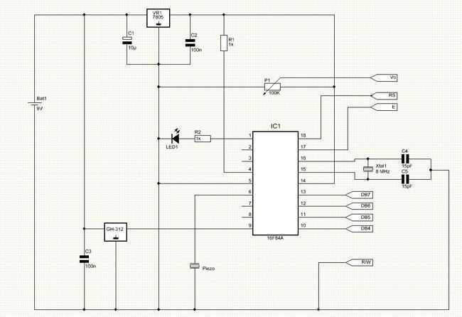
The transmitter is shown and although straightforward, there are a couple of tricks that I had to incorporate to minimise battery drain during standby. Although the PIC quiescent current is only 200uA, that will still flatten a pair of...
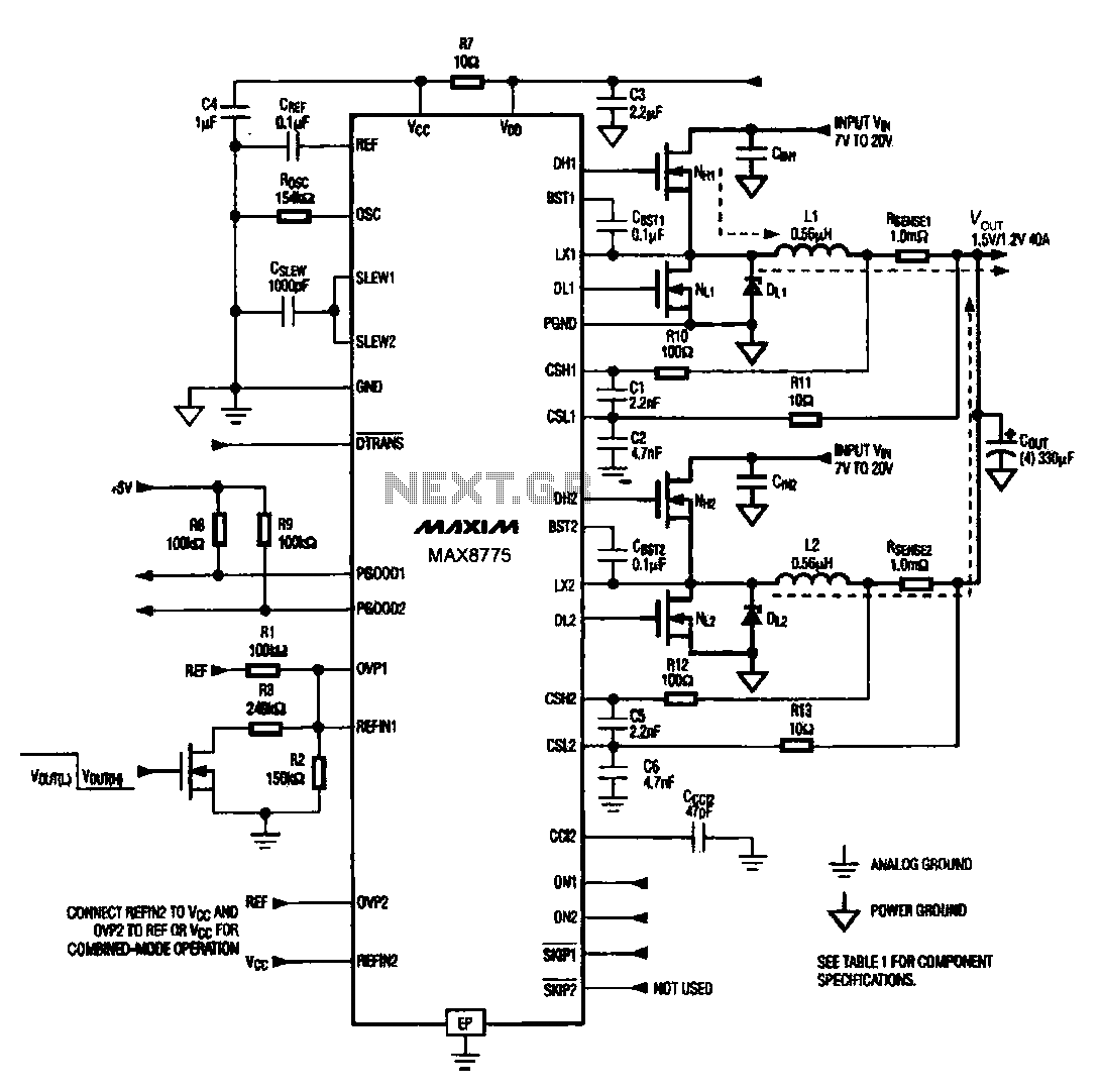
Notebook computer chip power supply circuit, which generates the PWM circuit using MAX8775. The notebook computer chip power supply circuit utilizes the MAX8775 integrated circuit to generate a Pulse Width Modulation (PWM) signal. The MAX8775 is a high-efficiency step-down voltage...