
Wien Bridge Oscillator Circuit

The Wien bridge oscillator is a type of electronic oscillator that generates sine waves. It utilizes a combination of resistors and capacitors to create a feedback network that establishes the frequency of oscillation. The circuit typically consists of an op-amp configured in a non-inverting amplifier configuration, where the gain is controlled by the resistive elements in the feedback loop.
The key components of the Wien bridge oscillator include two resistors (R1 and R2) and two capacitors (C1 and C2) arranged in a bridge configuration. The resistors and capacitors are selected to set the desired frequency of oscillation, which can be calculated using the formula:
f = 1 / (2πRC)
where R is the resistance and C is the capacitance in the feedback network. The op-amp amplifies the signal, and the feedback loop ensures that the output oscillates at the calculated frequency.
To maintain stable oscillation, the circuit requires a method for automatically adjusting the gain of the op-amp. This is often accomplished using a thermistor or a light-dependent resistor (LDR) in conjunction with a variable resistor to provide the necessary gain control. This automatic gain adjustment helps to stabilize the amplitude of the output signal and prevents distortion in the waveform.
The output of the Wien bridge oscillator is a clean sinusoidal waveform, making it suitable for various applications, including audio signal generation, function generators, and testing equipment. The use of a rail-to-rail op-amp enhances the performance of the circuit by allowing the output voltage to swing close to the supply rails, maximizing the usable output range. The Wien bridge oscillator is valued for its simplicity, stability, and effectiveness in producing high-quality sine wave signals.This is a circuit that is known as wien bridge oscillator circuit. The circuit has positive and negative feedback loop. This circuit is work with control by op amp. This is the figure of the circuit. The circuit oscillates at a frequency determined by the RC time constant at frequency and produces a sinusoidal waveform at the output voltage Vout. In many cases this circuit is used as sine wave generator which is using rail to rail op amp. [Schematic`s diagram source: Advanced Linear Devices, Inc] 🔗 External reference
Related Circuits
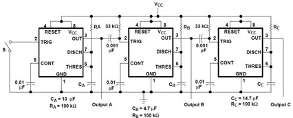
A sequential timer circuit device is utilized in various applications for initializing conditions during start-up or for activating test signals in sequences, such as in test equipment devices. The circuit diagram below illustrates a sequencer circuit with potential applications...
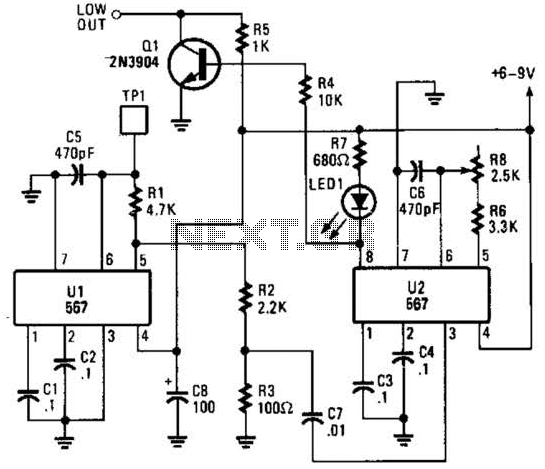
When the touch switch SI is activated, resistor R4 is driven high, causing the control voltage to rise, which latches the switch. Conversely, when switch S2 is activated, resistor R4 goes low, resulting in a decrease in the control...
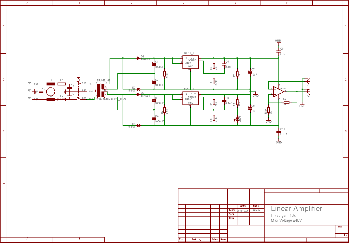
The aim of this project was to develop a linear analogue amplifier designed for laboratory use. This amplifier has to realise a voltage amplification of 10x and is intended to amplify function generator signals for tests. Power supply requirements:...
This is a straightforward infrared detector circuit designed to detect infrared light. The circuit comprises only three components: an RS-276-145 photo transistor, a 330-ohm resistor, and a general-purpose LED (Light Emitting Diode). When the photo transistor receives infrared light...
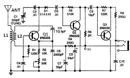
All coils are designed using an inch diameter PVC pipe with 20-gauge insulated hookup wire. L1 requires 6 turns, while L2 requires 14 turns. Additional turns can be added or subtracted from L1 or L2 (or C2 can be...
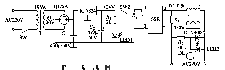
An AC solenoid-driven control circuit utilizing the SSR principle is illustrated. When switch SW1 is closed, a 220V AC transformer steps down the voltage to 30V AC through transformer T. The circuit includes a rectifier, capacitor C, and a...