
Metal detector using 555

The metal detector circuit utilizes the 555 timer IC in an astable mode configuration, which allows it to produce a continuous square wave output. The frequency of this output is influenced by the presence of metal or magnets in proximity to the sensing coil (L1). The circuit includes a choke of 10mH, which serves as an inductor that, in combination with the coil, creates a resonant circuit.
When a metal object is detected, the inductance of the coil changes, which in turn alters the oscillation frequency produced by the 555 timer. This change in frequency is significant enough to be detected by the circuit and is used to drive an 8-ohm speaker, producing an audible sound as a response to the detected metal.
The power supply for this circuit must provide a stable DC voltage in the range of 6 to 12 volts. This allows for flexibility in the choice of the power source, whether it be batteries or an external power adapter. The simplicity of the design, requiring only a few external components such as resistors, capacitors, the choke, and the speaker, makes it an accessible project for beginners in electronics.
The circuit can be further enhanced with additional features, such as sensitivity adjustments or visual indicators (like LEDs), to improve the user experience. However, the fundamental operation relies on the interaction between the 555 timer, the inductor, and the detection of metal through changes in oscillation frequency.A very simple metal detector electronic project can be designed using a simple 555 timer integrated circuit . As you can see in the schematic circuit , this electronic project requires few external electronic parts .
This circuit detects metal and also magnets. When a magnet is brought close to the 10mH choke, the output frequency changes. This metal detector project can be powered from a power supply that can provide an output DC voltage between 6 an 12 volt . If a metal is closer to the L1 coil , will produce a change of output oscillation frequency, that will generate a sound in the 8 ohms speaker .
🔗 External reference
Related Circuits
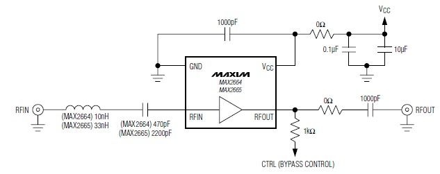
These devices feature a broadband low-noise amplifier (LNA) with an integrated bypass switch. The MAX2664 operates within the UHF frequency range of 470 MHz to 860 MHz, while the MAX2665 functions within the VHF frequency range of 75 MHz...
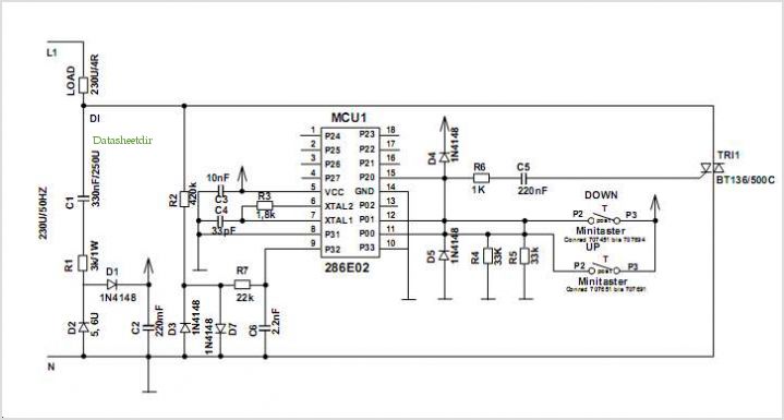
Introduction The ignition timing lights commonly used range from simple neon to complex units. Neon timing lights have a drawback due to their low light output, necessitating operation in subdued lighting. This presents a safety hazard, as users tend...
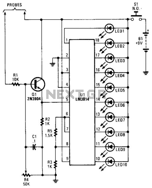
A bar-graph LED driver is utilized to control 10 LEDs, providing a relative indication of moisture levels. The moisture probes are connected in such a way that the electrical conductivity resulting from moisture tends to forward bias transistor Q1,...
This type of sensor switch is ideal for creating touch-operated bells and buzzers in small toys, which function for a limited duration before automatically shutting off. The trigger's input impedance is very high, allowing the touch sensor switch to...
This water level alarm circuit can be utilized as a water level indicator to monitor the desired water level in various applications, such as tanks, swimming pools, or any location where water is stored. The circuit is constructed using...
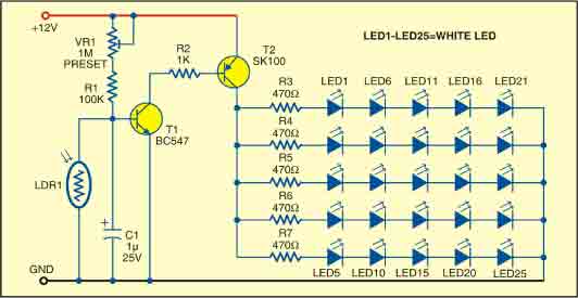
This sunlight-controlled lamp utilizes a light-dependent resistor (LDR) as the sunlight sensor and comprises a total of 25 high-brightness white LEDs. Each row of LEDs is connected in series with separate resistors. The operation of the circuit is straightforward....