
Metal detector with CD4011
The described metal detector circuit operates on the principle of frequency modulation and interference, utilizing two oscillators to create a detectable signal when in proximity to metallic objects. The primary oscillator, constructed from NAND gate N1, generates a stable frequency of 470 kHz, facilitated by a ceramic filter. This frequency serves as a reference for the second oscillator, which is formed with NAND gate N3 and an inductor-capacitor (LC) combination. The LC circuit is tuned to produce a frequency that, when mixed with the reference frequency, results in an audible beat frequency that can be detected by the user.
The output from the variable oscillator is routed through NAND gate N4, where the signal is amplified to ensure sufficient strength for detection. The critical component of the system is the sensor coil, designated as L1, composed of 70 turns of enameled copper wire with a diameter ranging from 0.3 mm to 0.6 mm, wound around a core with a diameter of 5 cm. This coil acts as an inductor and is sensitive to changes in its magnetic field caused by nearby metallic objects. When the coil approaches a metal object, the change in auto-induction alters the oscillation balance, resulting in a variation in the output sound. This audible signal indicates the presence of metal, allowing the user to identify potential targets effectively.
The design emphasizes simplicity and cost-effectiveness, making it accessible for hobbyists and educational purposes. The use of CD4011 integrated circuits and readily available components further enhances the feasibility of constructing this metal detector. The circuit can be powered by a standard battery, ensuring portability and ease of use in various environments. Overall, this metal detector represents an effective application of basic electronic principles to achieve practical functionality in detecting metallic objects.The working principle of this cheap and easy to build metal detector circuit consists in mixing two equal frequencies which causes a low-frequency interference. When one of the oscillators become unstable then the frenquency of the interference will be modified.
The metal detector circuit is built with CD4011. The oscillator is built with NAND N1 and a ceramic filter of intermediary freq. (470kHz). The second oscillator is with N3 and a LC combination. The freq. of this osc. is adjusted in such way that will produce an audible oscillation of both freqs. Thru N4, the signal from the variable osc. is amplified. If the sensor coil L1 is closer to a metal object then it will modify the auto-induction of the coil, the osc. is unbalanced and the sound will modify. The metal detectors coil is made of: 70 turns of enamelled copper with diam. of 0.3-0.6 mm on a 5 cm diam. 🔗 External reference
Related Circuits
This is a very basic infrared detector/emitter circuit. One major downside of this circuit, is that ambient infrared light will interfere with its detecting obstacles. The described circuit functions as a basic infrared (IR) detector and emitter system, commonly utilized...
The design originated from the interest in discovering a new technique for analog to digital conversion. The two types of ADC (Analog to Digital Converter) that influenced the development of this circuit are the Flash Type ADC and the...

This audio peak detector enables the monitoring of a pair of stereo channels using a single LED. The circuitry employed for both the left and right channels is identical. The audio peak detector circuit is designed to provide a visual...
This circuit detects metal and also magnets. When a magnet is brought close to the 10mH choke, the output frequency changes. The circuit operates on the principle of inductance variation in response to the presence of a magnetic field. The...
This circuit detects motion within approximately 5 inches of a piezo-ceramic element ultrasonic transducer. The detection distance is much smaller than obtainable with other ultrasonic techniques; however, it only requires a single transducer, as opposed to the two-transducer arrangement...
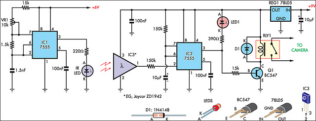
This circuit serves as an alternative to the infrared (IR) beam break detector featured in the June 2009 issue of Silicon Chip. To enhance its insensitivity to ambient light, it employs a standard IR receiver integrated circuit (IC), such...