
Metal detector with 555

The circuit operates on the principle of inductance variation in response to the presence of a magnetic field. The core component is a 10mH choke, which is an inductor designed to resist changes in current. When a magnet approaches the choke, the magnetic field interacts with the inductor, resulting in a change in inductance. This change affects the resonant frequency of the circuit, which can be detected and measured.
The circuit typically includes a signal generator, which produces an oscillating signal at the resonant frequency of the inductor. The output from the inductor is fed into a frequency detection circuit, which could be implemented using a microcontroller or a dedicated frequency counter. The detection circuit monitors the frequency of the output signal and triggers an alert or activates a response mechanism when a significant deviation from the baseline frequency is detected.
To enhance sensitivity and reduce false positives, additional components such as capacitors may be included to form a resonant LC circuit with the inductor. The values of these components can be adjusted to fine-tune the circuit's response to specific magnetic fields or metal types. A comparator circuit may also be integrated to provide a clear digital output based on the detected frequency change, allowing for easy interfacing with other electronic systems or alarms.
This type of metal and magnet detection circuit can be utilized in various applications, including security systems, industrial automation, and proximity sensing in consumer electronics.This circuit detects metal and also magnets. When a magnet is brought close to the 10mH choke, the output frequency changes. 🔗 External reference
Related Circuits
This is a circuit which I originally included in my book, 22 Tested Transistor Projects, published by Babani Press in 1976 (ISBN 0 900162 63 S). It is one I had great fun with. It uses the PUT Complimentary...

The difference between instantaneous frequency and central frequency of the carrier is directly proportional to the instantaneous value of the amplitude of the message signal. A 555 Timer configured in Astable Mode can be utilized for generating Frequency Modulated...
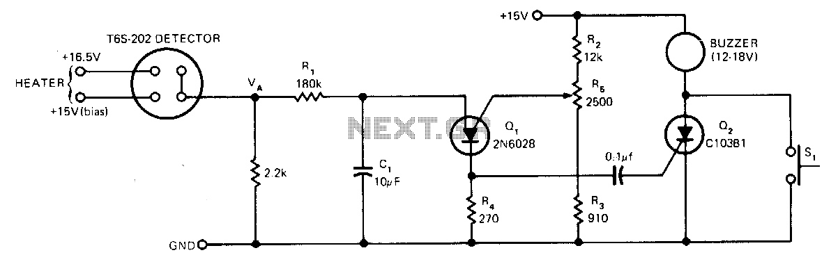
The sensor operates based on the selective absorption of hydrocarbons by an n-type metal-oxide surface. The device features a heater designed to eliminate hydrocarbons once smoke or gas is no longer detected in the immediate vicinity, allowing for reuse....
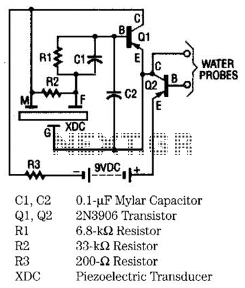
The moisture detector utilizes two transistors and a piezoelectric transducer to emit an alarm tone when water is detected. Transistor Q1 functions as a crystal-controlled oscillator, employing a portion of the piezoelectric transducer XDC, which consists of two piezoelectric...
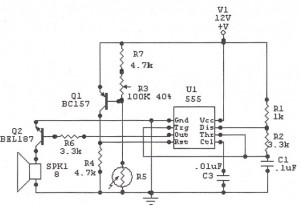
The following circuit illustrates a Sun Up Alarm Light Alarm Circuit Diagram. This circuit is based on the 555 Integrated Circuit (IC). Features include simplicity and cost-effectiveness. The Sun Up Alarm Light Alarm Circuit employs the 555 timer IC in...
The first positive pulse from a classic 555-based oscillator is always 1.6 times longer than the subsequent pulses. This discrepancy occurs because, during the initial cycle, capacitor C2 begins charging from 0 V. While this is typically not an...