
Digital delay circuit lamp circuit 2

The digital delay lamp circuit is designed to provide a controlled delay in the operation of a lamp using a 2-input NAND gate integrated circuit. The circuit begins with a capacitive voltage rectifier that ensures a stable DC voltage supply. The two NAND gates are configured such that the output responds to changes in the input states, specifically focusing on the transition from low to high.
Upon energization, the initial state of the NAND gates is crucial. Both inputs are typically held at a high logic level (1), which keeps the output of one gate in a low state (0). This is due to the steady state conditions of the circuit, where the charging of capacitors influences the logic levels. When an external switch (SB) is pressed, the first input transitions from low to high, triggering a change in the output state. The output of the first gate switches to low, allowing current to flow through diode VD1, which then influences the second input of the second NAND gate.
As the second input also goes low, the output of the second NAND gate transitions to high, energizing the relay (K) that powers the lamp (E). This relay operation is critical as it provides a physical connection to the lamp, allowing it to illuminate. The design includes a timing element, where after the button is released, the output remains high for a period determined by the RC time constant of the charging circuit. The time constant is influenced by the values of the resistors and capacitors used in the circuit.
After approximately 40 seconds, the charge on the capacitor reaches a level that causes the output to lose its low state, deactivating the relay and turning off the lamp. The circuit design emphasizes the importance of grounding the input sides of the NAND gates to prevent interference, ensuring reliable operation. The use of high-quality components, such as CBB polypropylene capacitors rated at 100V, and the selection of a suitable electromagnetic relay rated for DC12V, are essential for the longevity and performance of the circuit. Overall, this digital delay lamp circuit effectively demonstrates the application of logic gates in practical electronic designs, providing both functionality and a delay mechanism for controlling lighting.A 2-input NAND gate integrated circuit fabrication of digital delay lamp circuit, VD3, vs, after Composed of simple capacitive voltage rectifier buck crossing the half line, th e circuit is energized, C. A terminal is output ipv about the stability of the entire controller DC voltage power supply. Figure, the door I the door O feet and the feet of are usually island level 1, so that both open state, while the other gate II input That is due to the end of foot in steady state C: it has charged the wires, so it is high level 1 so the door. II output terminal pin low level state, the diode VT end, the relay K little trick. E lamp does not light when pressed SB, by R. power to (j g of electricity, so that the door I input feet from the original low-to-high level 1 state, the output goes low O state, diode VDI conduction, such as on the adoption of VDI discharge.
therefore, another rjU the one input terminal feet becomes a low level. state, the output terminal pin goes high l state, high hills l level NIE Yi Rt make wr conduction, the relay K is energized, its power make contact k1 is closed, the lamp is powered hair E dagger when released SB, f1 T and the output goes high l, VD1 off, f. but also by R. charging about after 40s time (depends on R, and (1, wide electrical time constant), f. F level rose to a certain value, the door lose meaning. low., VT end, K release, lamp E goes out. door 1, f] [I can CD1011 digital integrated circuits inside two intact and two NAND gates brother does not use NAND gates should the grounding of all its input side, to eliminate possible interference caused .c.
requires the use of CBB, lOOV polypropylene capacitors and other type K with JZC-22F, DC12V power in a small electromagnetic relay.
Related Circuits
This lie detector circuit diagram provides two readings: one for challenging questions directed at the subject and another to display the subject's emotional state in general. The emotional states are detected not only by heart rate variations and perspiration...
The SL517 is designed as an audio, RF, or infrared decoder circuit suitable for electronic toy applications. The internal circuitry consists of an analog amplifier, a frequency divider, a bistable circuit, and a driver. It utilizes CMOS technology, has...
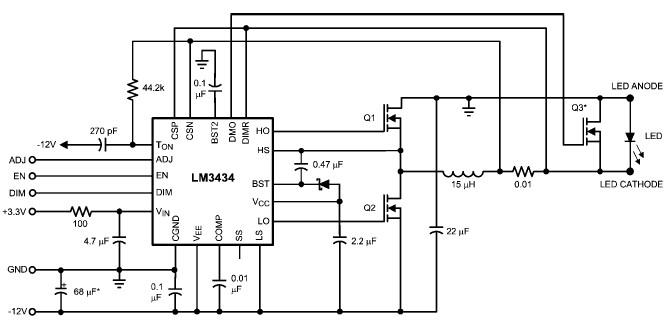
The LM3434 adaptive constant on-time DC/DC buck (step-down) constant current controller can be used to design a simple high-power LED driver application. The LM3434 provides a constant current for illuminating high-power LEDs. The output configuration allows the anodes of...
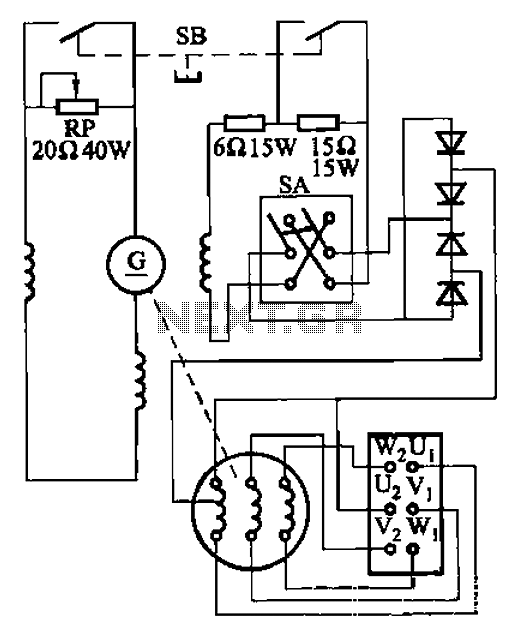
The AX3-300-2 DC arc welding machine circuit is part of the AX, AX1, AX3, and AR series of rotary DC arc welding machines. These machines share a similar structural design, featuring a three-integral unit configuration that combines an inverter...
This circuit features a microphone and preamplifier that take precedence over any other audio signal, functioning similarly to a one-way intercom. When the push-to-talk switch is activated, the main amplifier switches from music playback to the voice signal. Essentially,...
This automatic NiCd charger for 9V NiCd batteries utilizes the properties of a 555 timer and is straightforward to construct. The design allows for continuous charging of the battery without the risk of overcharging or discharging. With the specified...