Digital weight scale
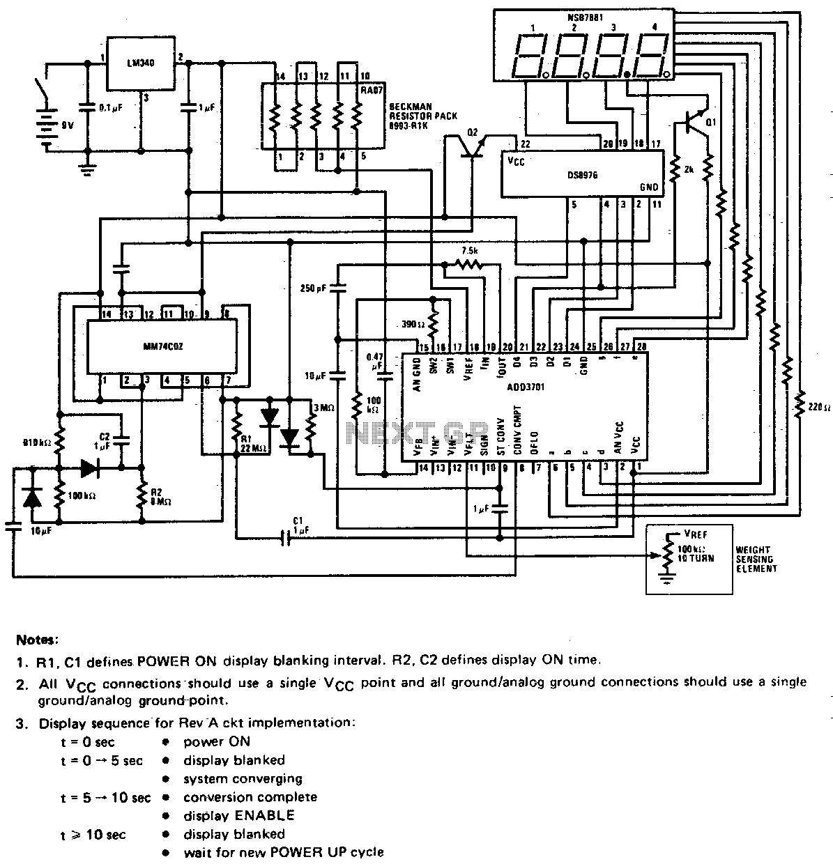
This circuit utilizes a potentiometer as the weight sensing element. An object placed on the scale displaces the potentiometer wiper by an amount proportional to its weight. The conversion of the wiper voltage to digital information is carried out, decoded, and interfaced with the numeric display.
The circuit operates by integrating a potentiometer, which serves as a variable resistor that changes its resistance based on the position of its wiper. When a weight is applied to the scale, the wiper moves, altering the resistance and consequently the voltage output across the potentiometer. This voltage change is directly proportional to the weight applied, allowing for accurate weight measurement.
The output voltage from the potentiometer is then fed into an analog-to-digital converter (ADC). The ADC translates the analog voltage signal into a digital format suitable for processing. This digital signal is subsequently decoded by a microcontroller or a dedicated decoder circuit, which interprets the value and prepares it for display.
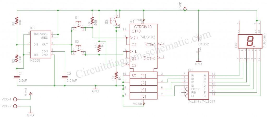
The microcontroller interfaces with a numeric display, typically a seven-segment display, to present the weight measurement in a user-friendly format. The display is updated in real-time, providing immediate feedback on the weight applied to the scale. Additional components such as resistors and capacitors may be employed in the circuit to ensure stability and accuracy in readings, as well as to filter any noise from the voltage signal to enhance the precision of the weight measurement system.
Overall, this circuit design effectively combines mechanical and electronic components to create a reliable weight measurement device.This circuit employs a potentiometer as the weight sensing element. An object placed upon the scale displaces the potentiometer wiper, an amount proportional to its weight Conversion of the wiper voltage to digital information is performed, decoded, and interfaced to the numeric display.
