
Meter Tester

This circuit utilizes a combination of switches (S1, S2, S3) and resistors (R12, R14, R15, Ru) to create a flexible testing environment for multimeters. The design allows for safe measurement of unknown meter parameters by employing a series connection that ensures identical current flow through both the multimeter (Ml) and the meter under test (M2).
The use of linear-taper potentiometers for R12, R14, and R15 enhances the precision of resistance adjustments, allowing for fine-tuning of the circuit to achieve the desired readings. The initial setup involves setting SI to its maximum resistance and keeping S2 open, which establishes a baseline for further adjustments. As resistance is decreased in SI, the circuit is calibrated until M2 registers full scale, which indicates that the maximum current for the unknown meter has been established.
Once S2 is closed, the adjustments of R14 and R15 become crucial in obtaining a mid-scale reading on M2 while maintaining the same current reading on Ml. This step is essential for determining the internal resistance of M2, which can be calculated based on the known values of Ru and the resistances of R14 and R15. If M2's internal resistance is found to be below 470 ohms, R14 is adjusted to its maximum resistance, and S3 is closed, allowing for further calibration of the circuit.
This configuration is particularly advantageous for testing meters with unknown specifications, as it safeguards sensitive components and provides a straightforward method for determining operational parameters. The careful selection and arrangement of components ensure that the circuit operates efficiently and accurately, making it a valuable tool for electronics testing and measurement. This unit uses switches and resistors to provide a number of current ranges. It allows you to test most of the meters availabl e at surplus outlets, and without damaging the sensitive movements when you have no idea of internal resistance or full-scale current of the unit. Ml is a multimeter set to measure current, and M2 is the meter-under-test. Starting with SI set at the maximum resistance and S2 open, decrease the resistance setting of SI, fine tuning with R12, until M2 reads full scale.
Then, read Ml. It will tell you the full-scale current for the unknown meter. As the meters are connected in series, the same current flows through both. Now, close S2 and adjust R14 and R15 until M2 reads exactly mid-scale and Ml reads the same current as determined earlier to be the maximum current for M2. Half the current is flowing in M2 and half is going through R14 and R15. The voltage drop is the same across the meter and R14 and R15, because they"re in parallel. Thus, the sum of the resistance of Ru and ii5 is the same as the internal resistance of meter M2. If the internal resistance of M2 is less than 470, set R14 at maximum resistance and close S3. Readjust R14. Both R14 and R12 should be linear-taper potentiometers.
Related Circuits
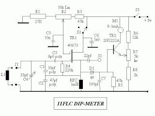
This circuit was developed by Luigi Falcone, I1FLC. It utilizes seven plug-in coils that cover a frequency range from 3.0 to 30 MHz within a Colpitts oscillator configuration. A coaxial socket, labeled J2, allows for the connection of a...
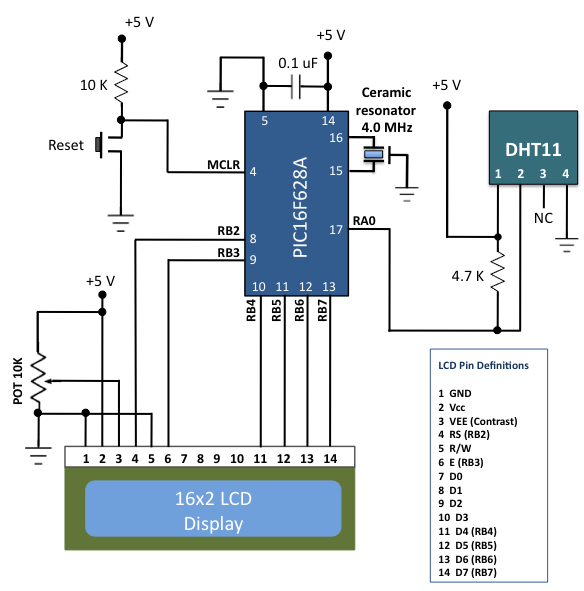
The DHT11 is the most affordable sensor currently available in the market that provides calibrated digital outputs for temperature and relative humidity. The DHT11 sensor is a low-cost digital sensor that measures both temperature and relative humidity. It operates...
A digital multimeter is a highly versatile instrument that integrates multiple measurement functions within a single unit. Typically, a multimeter encompasses the functionalities of a variable-range ohmmeter, voltmeter, and ammeter, with some models also capable of testing diodes and...
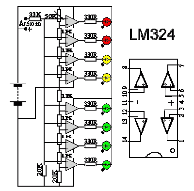
The 1K resistors in the circuit are essential for enabling the LEDs to activate at varying audio levels. This circuit is easily expandable with additional operational amplifiers and is not restricted to the use of the LM324. The 33K...
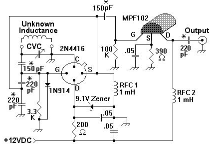
A device for measuring inductance. Over the years, articles describing devices for measuring inductance have appeared in QST and elsewhere, but none of them were suitable, so a new device has been developed. The inductance measurement device is designed to...
A portable CD player, radio, cassette player, a couple of microphones, and a PC sound card are connected to the inputs of an audio mixer. The output of the mixer is connected to a pair of active loudspeakers. The...