
One second Audible Clock Circuit Schematic

The circuit design features a CMOS 4024 chip, which serves as a counter and frequency divider, enabling the generation of a precise one-second pulse. The high input impedance at pin #1 allows for easy signal detection, ensuring that the circuit can operate effectively without complicated setups. The use of diodes in the configuration is crucial for controlling the flow of current and ensuring that the correct frequency division occurs. The modification for 60Hz operation illustrates the adaptability of the circuit to different mains frequencies, enhancing its versatility in various geographical locations.
The optional visual display provides an additional method for users to confirm the timing of the pulses visually. The choice of resistor R3 is critical; it must be selected based on the supply voltage to ensure the proper functioning of the LED without risking damage to the components. This circuit is ideal for applications in timing, metering, and other electronic devices where accurate timing signals are essential. Overall, the simplicity of the design, combined with the effectiveness of the components used, makes this one-pulse-per-second clock a practical solution for a range of electronic timing applications.This accurate one-pulse-per-second clock is made with a few common parts and driven from a 50 or 60 Hertz mains supply but with no direct connection to it. A beep or metronome-like click and/or a visible flash, will beat the one-second time and can be useful in many applications in which some sort of time-delay counting in seconds is desirable.
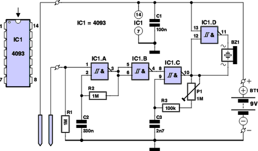
Th e circuit is formed by a CMos 4024 counter/divider chip and 3 diodes, arranged to divide the frequency of the input signal at pin #1 by 50 (or 60, see Notes). The input impedance at pin #1 is very hight, so simply touching the pin (or a short track or piece of wire connected to it) is usually enough to provide the necessary input signal.
Another way to provide an input signal consists in a piece of wire wrapped several times around any convenient mains cable or transformer. No other connection is necessary. To allow precise circuit operation in places where the mains supply frequency is rated at 60Hz, the circuit must be modified as follows: disconnect the Cathode of D1 from pin #11 of IC1 and connect it to pin #9.
Add a further 1N4148 diode, connecting its Anode to R1 and the Cathode to pin #6 of IC1: that`s all! The visual display, formed by D4 and R3 is optional. Please note that R3 value shown in the Parts list is suited to low battery voltages. If 9V or higher voltages are used, change its value to 1K. 🔗 External reference
Related Circuits
The following circuit illustrates a fully linear diode sensor circuit diagram. This circuit is based on the A748 integrated circuit (IC). Features include the use of an operational amplifier (op-amp). The fully linear diode sensor circuit utilizes the A748 IC...
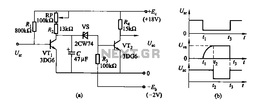
The delay time ranges from 0.5 to 3.5 seconds, which can be adjusted using the potentiometer RP to modify the delay duration. The circuit utilizes a timing mechanism that allows for the adjustment of delay intervals between 0.5 seconds and...
Figure 2-32 (a) illustrates the time control diagram for a motor operated by switch S1. When S1 is set to position 1, the power driver circuit supplies current to the motor, enabling it to run. When S1 is switched...
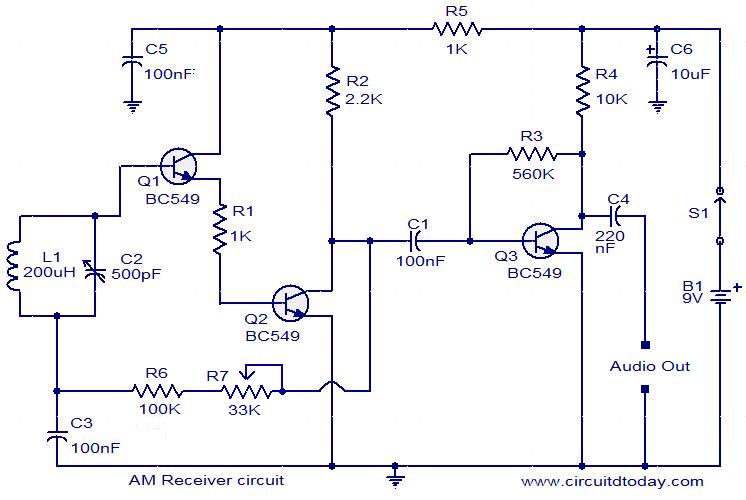
The following circuit illustrates an AM receiver capable of operating within the frequency range of 550 to 1100 KHz. Features include adjustments for sensitivity and selectivity of the circuit. The AM receiver circuit designed for the frequency range of 550...
Have you ever observed the stairs to an upper story in your house transform into a waterfall? Or perhaps you returned home to find your aquarium fish attempting to swim across the carpet? For your sake, it is hoped...

A 40673 dual-gate MOSFET is matched to a crystal filter operating at 45 MHz. The filter impedance is approximately 2 kΩ. The +4 V source can be adjusted to control the gain, ranging from +4 V to -4 V. The...