
Metronome Generator Circuit using NE555

The NE555 timer IC is a versatile component widely used in various applications, including timing, pulse generation, and oscillator circuits. In the astable multivibrator configuration, the NE555 operates continuously, switching between its high and low states, which results in a square wave output. This output can be used as a metronome, providing a consistent beat for musical practice.
The frequency of oscillation, which dictates the tempo of the metronome, is determined by the resistor values R1 and R2, as well as the capacitor C1. The formula for calculating the frequency (f) of the output signal in an astable configuration is given by:
f = 1.44 / ((R1 + 2 * R2) * C1)
In this equation, R1 is connected between the supply voltage and the discharge pin (pin 7) of the NE555, while R2 connects from pin 7 to the threshold pin (pin 6). The capacitor C1 is connected between pin 6 and ground. Adjusting the values of R1, R2, and C1 allows for fine-tuning of the output frequency to suit the needs of the user.
For practical implementation, the circuit typically includes a power supply, the NE555 IC, resistors R1 and R2, capacitor C1, and output components such as a piezo buzzer or LED indicator to provide audible or visual feedback. The circuit can be easily assembled on a breadboard or a printed circuit board (PCB) for more permanent applications. This simple yet effective metronome circuit serves as an excellent project for electronics enthusiasts and music learners alike.Welcome to the weblog where we discuss about electronic circuits schematics, PCB design, diy kits and electronic projects diagrams. Here is a simple circuit with NE555 IC that can be used to generate metronomes. Such circuit is very useful for those who learn music. The circuit is simply an astable multivibrator NE555 cable around. The components R1, R2 and C1 determine the frequency 🔗 External reference
Related Circuits
Related components PDF download: ICL7106CD4036. The LCD electronic thermometer circuit is illustrated. The temperature sensor KTY10 exhibits a strong linear relationship between temperature and resistance. Points A and B (Measurement display circuit) can be connected with a 100-meter wire....

The text of the Arduino reference is licensed under a Creative Commons Attribution-ShareAlike 3.0 License. Code samples in the reference are released into the public domain. The Arduino platform is an open-source electronics prototyping environment that enables users to create...
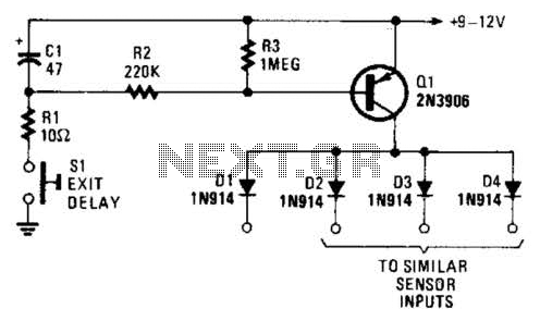
Depressing SI charges CI to the supply voltage. This biases Q1 on via bias resistors R2 and R3. A voltage is available for the duration of the delay period to hold off the alarm circuit. CI can be increased...

This circuit diagram illustrates a triangular wave generating circuit utilizing a pair of operational amplifiers (Op-Amps). The LM741 Op-Amp is recommended for this application. The first Op-Amp, located on the left, functions as a comparator, while the second Op-Amp...
An RF probe is a circuit designed for testing equipment that converts high-frequency signals into DC voltage. This conversion facilitates the measurement of RF voltages for testing or adjusting transmitters, receivers, and modulators. The RF probe circuit outlined here...
The LED blinks as expected, then pauses for an indefinite duration, flashes again a different number of times, and turns off again, displaying no discernible cyclic behavior. It activates without any external input, indicating that there is likely no...