
RF Probe Circuit

The RF probe circuit typically consists of a diode, a resistor, and a capacitor arranged in a configuration that allows for efficient signal detection and conversion. The diode serves as the primary component for rectifying the incoming RF signal. When the RF signal is applied to the circuit, the diode conducts during the positive half-cycle, allowing current to flow through the load resistor. The resulting voltage across the resistor is proportional to the RF signal's amplitude.
To enhance the circuit's performance, especially at higher frequencies, a bypass capacitor is often included in parallel with the load resistor. This capacitor helps to stabilize the DC voltage output by filtering out any high-frequency noise that could affect the measurement accuracy. Additionally, the choice of components, such as the diode type and the resistor value, is crucial for optimizing the probe's response across the desired frequency range.
For practical applications, the RF probe can be connected to an oscilloscope or a voltmeter to visualize or quantify the rectified signal. Calibration of the probe may be necessary to ensure accurate voltage readings, particularly when measuring signals at the upper end of the specified frequency range. It is also essential to maintain proper grounding techniques to minimize interference and ensure reliable measurements.
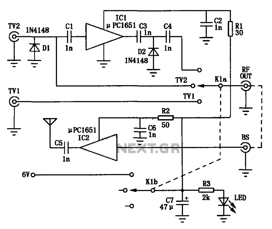
In summary, the RF probe circuit is a valuable tool for engineers and technicians working with RF equipment, providing a straightforward method for measuring RF voltages across a wide frequency spectrum while emphasizing the importance of component selection and proper usage to maintain measurement integrity.A RF probe is a circuit for testing equipment that converts a high frequency signal into a DC voltage. In this way it is very easy to measure RF voltages for either testing or adjustments of transmitters, receivers, modulators.
The RF probe circuit described here is suitable for signals with the frequency range from about 100 kHz to 1000 MHz. Alth ough the diode used here can, in principle, go up to 3 GHz, the impedance of the ground connection will adversely influence the measurement at very high frequencies. Also, please keep in mind to use this probe only on low RF power. 🔗 External reference
Related Circuits
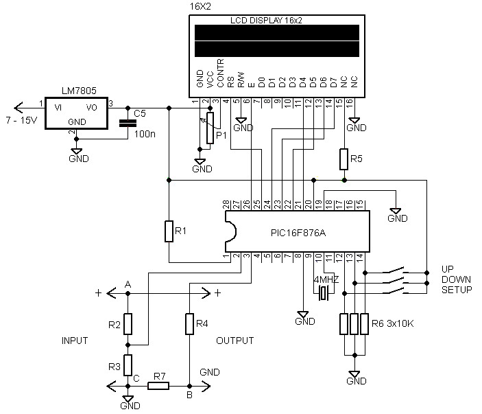
A voltmeter and ammeter using a PIC microcontroller can measure voltage and current simultaneously. This setup employs a PIC16F876A as the data processor for voltage and current measurements. An LCD display (16x2) is utilized to present the measured voltage...
The following circuit illustrates the Weller WLC100 Electronic Soldering Station Circuit Diagram. This circuit utilizes the Q4012LPH Transistor. Features include safety measures, temperature control, and functionality as a soldering station that performs effectively for various applications. It is a...
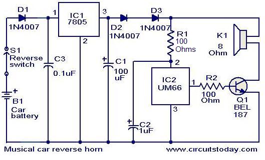
This circuit is designed to produce a musical horn whenever a car is in reverse gear. It utilizes two integrated circuits (ICs) for its operation: a voltage regulator (7805, referred to as IC1) and a musical tone generator (UM66,...
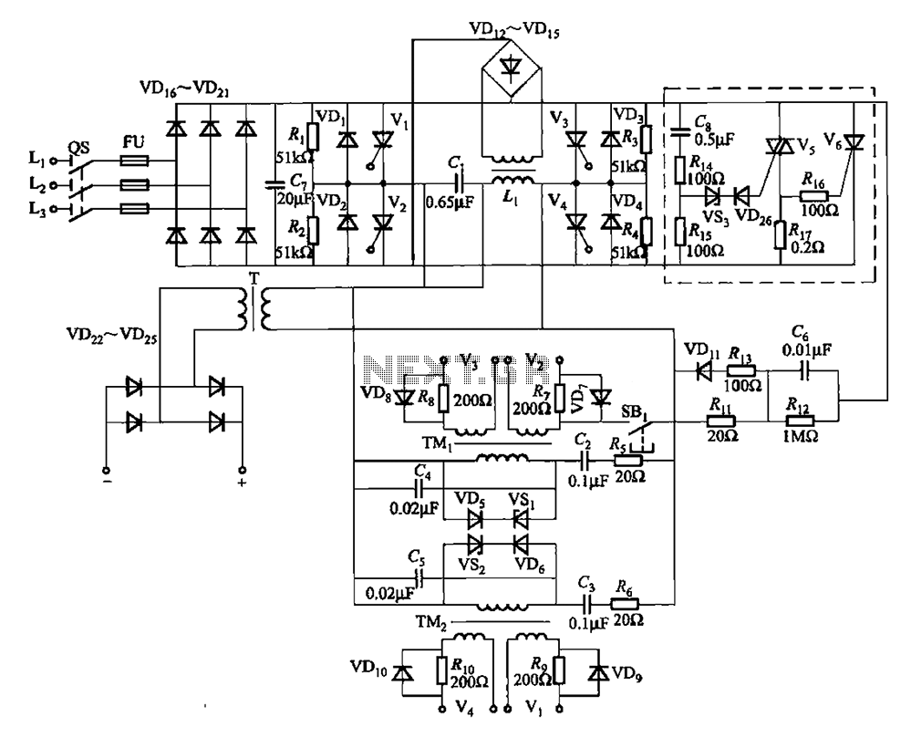
A 25kHz thyristor inverter welding machine circuit utilizes high-frequency operation to enable smaller transformer designs. The circuit diagram is illustrated in Figure 9-14. The no-load output voltage of the machine is 45V DC, with a peak voltage of 90V...
Amplification is utilized to convert video output signals from various devices, such as VCRs and DVD players, which often require amplification of weak output signals. Additionally, it can transmit radio frequency signals over a radius of approximately 7 meters,...
A bandpass filter allows a specific range of frequencies to pass while rejecting frequencies that fall outside the upper and lower limits of the passband. The frequencies that are permitted to pass are referred to as the passband, which...