
LCD electronic thermometer circuit

The LCD electronic thermometer circuit employs the ICL7106CD4036 integrated circuit, which is designed for digital temperature measurement applications. The KTY10 temperature sensor is a vital component, known for its accurate and linear resistance-temperature characteristics, making it suitable for precise temperature readings.
In this circuit, the KTY10 sensor converts temperature variations into corresponding resistance changes, which are then processed by the ICL7106. The ICL7106 is a dual-slope analog-to-digital converter that provides high accuracy and stability in measuring the analog voltage output from the KTY10 sensor.
The measurement display circuit, which can be placed up to 100 meters away from the sensor, utilizes a 3-wire connection to minimize signal degradation over distance. This configuration ensures that the digital output remains accurate despite the extended wiring.
The digital display of the thermometer is capable of showing temperatures in the range of -50°C to +150°C, making it suitable for various applications, including environmental monitoring, HVAC systems, and industrial processes. The LCD screen provides a clear and easy-to-read output, which enhances user interaction and data interpretation.
Overall, this electronic thermometer circuit combines precision sensing, effective signal processing, and user-friendly display features, making it a robust solution for temperature measurement needs.Related components PDF download: ICL7106CD4036 The LCD electronic thermometer The LCD electronic thermometer circuit is as shown. The temperature sensor KTY10 has good linear relationship between temperature - resistance, and you can connect point A and point B (Measurement display circuit) with 100m wire, the digital display range is -50?
to +150?, the.. 🔗 External reference
Related Circuits
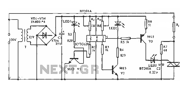
The circuit utilizes a built-in temperature sensor to control the triac TC620 for temperature regulation. The adjustment circuit consists of resistors Rp1 and Rn, which can be modified to set both the lower and upper temperature limits. LED1 illuminates...
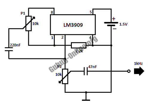
This circuit design for a high-frequency waveform generator is highly beneficial for electronic experiments and designs. The circuit generates sine wave oscillations, but it can also be modified to produce triangle or square wave functions. The high-frequency waveform generator circuit...
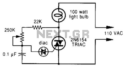
A phase-controlled dimmer delays the triac turn-on to a selected point in each successive AC half cycle. This circuit is suitable only for incandescent lamps, heaters, soldering irons, or universal motors that have brushes. A phase-controlled dimmer is an electronic...
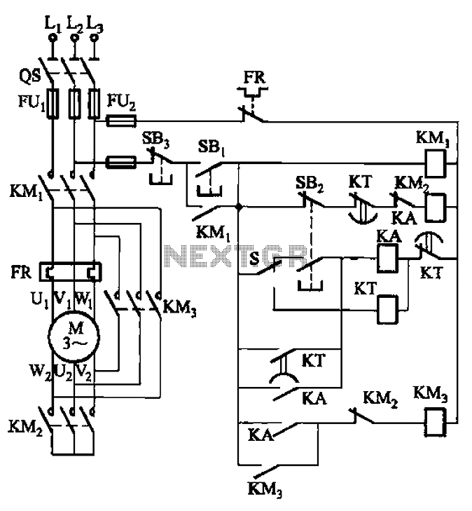
The circuit is depicted. It is capable of both manual and automatic control. The circuit in question is designed to facilitate dual modes of operation: manual and automatic control. This versatility allows users to engage with the system according to...
This is a stereo power amplifier circuit that operates at up to 22W per channel, resulting in a total output of 2x22W. A few external components are required to support the main component, the TDA1554. A heatsink on the...
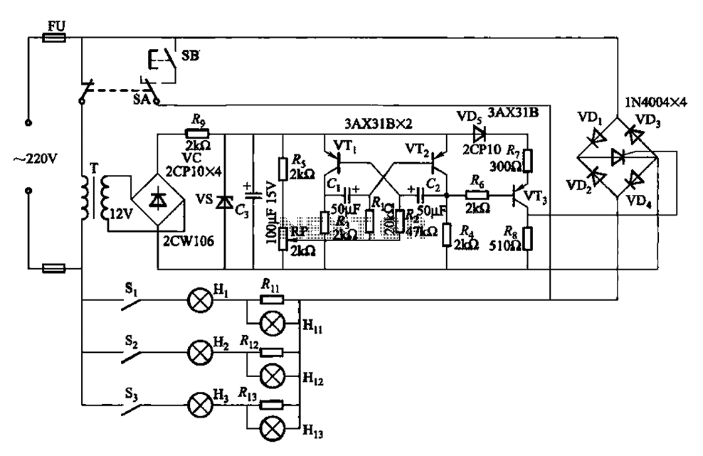
The self-excited multivibrator circuit utilizes transistors VTi and VT2 to generate an output signal that triggers a thyristor (VT3). An adjustment potentiometer (RP) is incorporated to modify the oscillation frequency, which in turn adjusts the flashing cycles of lights...