
MIC29150-5.0 by the MIC29152-12 dual output voltage regulator circuit

The dual output voltage regulator circuit utilizes the MIC29150 series from Micrel, which are low-dropout (LDO) voltage regulators designed for various applications requiring stable output voltages. The MIC29150-12 provides a fixed output voltage of 12V, while the MIC29150-5.0 offers a fixed output of 5V.
In this configuration, both regulators are connected to a common input voltage source, which should exceed the maximum output voltage by at least the dropout voltage specified in the datasheet for each regulator. The circuit typically includes input and output capacitors to ensure stability and transient response.
The input capacitors, usually ceramic or tantalum types, help filter any noise from the supply line and provide a stable voltage to the regulators. The output capacitors are essential for maintaining stability and minimizing voltage ripple at the output. The choice of capacitor values is critical and should align with the manufacturer's recommendations to ensure optimal performance.
Additionally, each regulator may have its own enable pin, allowing for independent control of the output voltages. This feature can be useful in power management applications where specific voltage outputs are only needed at certain times.
The overall design of this dual output voltage regulator circuit is efficient and cost-effective, making it suitable for a wide range of electronic devices requiring dual voltage levels. Proper thermal management should also be considered, as the regulators can dissipate heat under load, necessitating the use of heat sinks or adequate PCB layout for heat dissipation.
In summary, the dual output voltage regulator circuit featuring the MIC29150-12 and MIC29150-5.0 is an effective solution for applications needing both 12V and 5V outputs, ensuring reliable performance and stability. As shown in the low-cost dual output voltage regulator circuit consists of two pieces Micrel companys MIC29150-12 and MIC29150-5.0 regulator constituted.
Related Circuits
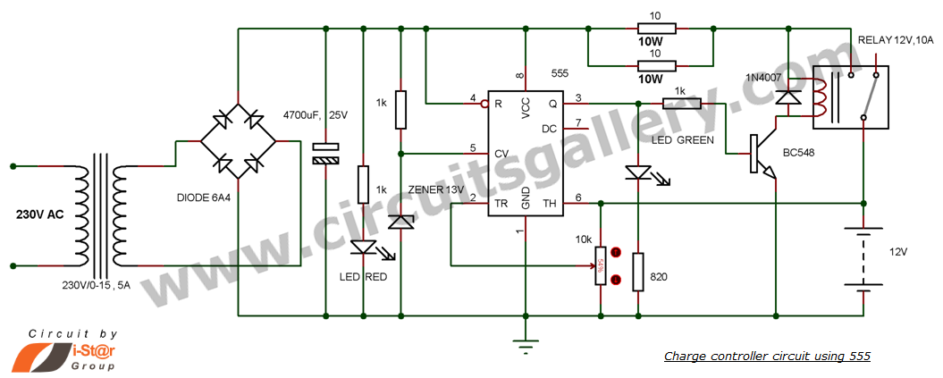
This is a simple DIY charge controller schematic created in response to a request from one of the readers on our Facebook page. The primary component of this automatic battery charger circuit is a 555 timer, which compares the...
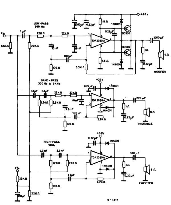
A simple multiway active speaker audio system can be designed using the TDA2030 audio IC. This TDA2030 active speaker audio system circuit is created to deliver optimal acoustic performance, as each loudspeaker is specifically designed and optimized for a...
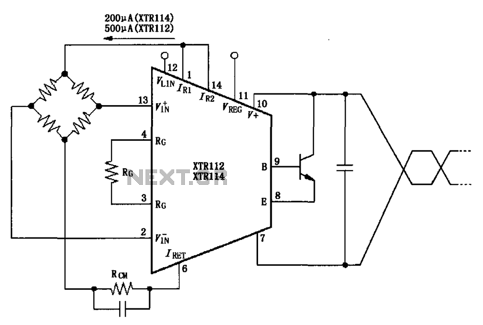
The two current sources within the chip (1 foot and 14 feet out) provide excitation. The output of each current source is 0.2 mA (XTR114) or 0.5 A (XTR112). The common mode input voltage is adjustable, ranging from 1.25...
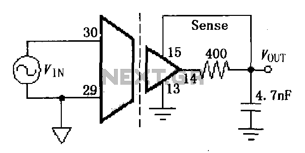
The ISO107 ripple reduction circuit includes an RC high-pass filter at the output to filter the output voltage ripple without impacting the DC characteristics. This configuration allows for a reduction of the 800kHz ripple voltage to less than 3mVp-p. The...
VCR Camera Video Detector Switch Controller Circuit. This video detector switch controller circuit utilizes the video output from a VCR or camera to... This circuit functions as a video detector switch controller, designed to manage the video output from a...
A simple active antenna can be designed using this electronic circuit diagram. This active antenna utilizes transistors and a few common electronic components. In the practice of short-wave frequency reception, a general rule is that a longer antenna will...